Very often, solar panels are installed rigidly and permanently. This is simple, but not very efficient, as during the day the sun moves across the sky and the amount of light energy received by the solar panels changes. The maximum return of the solar battery is possible only when the light falls on the panel perpendicular to its plane. In order for the sun's rays to fall on the solar panel always perpendicular. solar tracking systems of different designs and different levels of complexity are used. Although such a system complicates the installation of solar panels, it allows you to take the maximum from them. Solar panels are still not cheap, and we, by investing in them, certainly want to realize their full potential.
Often the simplest tracking systems can only rotate the panel in one axis. Such devices include a pair of photo sensors and a pair of comparators that control one electric motor included in the diagonal of the simplest H-bridge. Such devices, of course, also increase the efficiency of solar panels, but they do not do it very efficiently, since they work only within one axis. This article describes a very simple solar tracking system, which, however, can move the panel in two axes, which increases the efficiency of the solar array. During operation, the system continuously tries to position the panel so that its plane is always perpendicular to the incident sunlight and to get the maximum return of electricity from the battery. The tracking device follows the sun from dawn to the last rays of sunset and automatically resumes its work the next morning.
Device diagram contains the LM339 chip, which is four analog comparators in a common package. Two motors are controlled by a specialized L293D microcircuit - a dual H-bridge. In addition to microcircuits, the circuit diagram contains several discrete elements. Photoresistors LDR1 - LDR4 are used as light intensity sensors. These photoresistors determine the position of the solar panel relative to the sun's rays.
The photoresistor block together with the LM339 comparator generates control signals for the L293D motor driver. Photoresistors LDR1 and LDR2 are fixed in the corners of the solar panel on the X axis, in LDR3 and LDR4 - on the Y axis. low voltage levels.
Consider the algorithm of work system on the example of its part responsible for moving along the X axis. If the photoresistor LDR2 receives more light than LDR1, then the resistance of LDR2 becomes less than the resistance of LDR1. A higher voltage level appears at the inputs of comparators A1 and A2 (4, 7). In this case, a high voltage level appears at the output of comparator A2 (1). Motor M1 starts to rotate in one of the directions (say, counterclockwise), turning the solar panel.
If LDR1 receives more light than LDR2, then its resistance becomes less than the resistance of LDR2, thereby reducing the voltage at the comparator inputs (4, 7). At the output (2) of comparator A2, a high level appears and the motor begins to rotate in the opposite direction (say, clockwise). Tracking along the Y axis works in exactly the same way.
The figure below shows a possible design of a solar tracking system. The circuit can be assembled on a unified breadboard or a conventional printed circuit board can be routed for it.
After the use of solar panels for the production of electricity on an industrial scale, engineers and designers began to look for ways to increase the efficiency of such power plants. The total dispersion of the Sun's light, which is determined by the change in the direction of the fall of the sun's rays on the photocells, did not allow efficient use of solar panels throughout the daylight hours. A way out of this situation was found quite quickly - solar panels began to be installed on a movable base connected to a solar tracking system.
As you know, to obtain maximum power from solar panels, it is necessary that the sun's rays hit the plane of the batteries perpendicularly. With this direction of rays, the efficiency of solar panels can reach 50-55%. For permanently installed batteries, this figure can be reduced to 10-15% due to changes in the angle of incidence of sunlight.
The solar tracking device consists of two main parts:
1. The control scheme, which determines the position of the Sun. The simplest diagram of a solar tracking device or otherwise a tracker (Solar Tracker) is shown below. To determine the position of the Sun, two photoresistors are used. The scheme includes:
- LM1458 operational amplifier chip (K140UD20);
- transistors BD139 (KT815G, KT961A) and BD140 (KT814G, KT626V);
- photoresistors;
- diodes 1N4004 (KD243G);
- resistors and tuning resistors.

2. Mechanisms for turning and tilting batteries depending on the direction of the sun's rays. The tilt mechanism allows the use of such tracking systems in any geographic latitudes: when installing solar panels in an area that corresponds to 320 north latitude, the axis of the device must be rotated 320 relative to the horizon. The drives of all mechanisms of the tracking system are built on the basis of electric motors, which are affected by the control system. The electric motors and the control system are powered by the solar panels themselves, so such installations are autonomous.
As you can see, the scheme and device of the solar tracker are quite simple. Naturally, more complex systems are used on an industrial scale, but a similar scheme can be assembled independently for a household installation for the production of electricity based on solar panels.

The network contains a large number of ready-made schemes and solutions for solar tracking systems. So, if there is a need to improve the design of solar panels and increase their performance, there is always the opportunity to do it yourself.
A solar tracker is an electronic-mechanical system designed to point solar panels at the Sun. The system tracks the position of the Sun in the sky and controls a servo that rotates the panels in the appropriate direction. The use of such a tracker allows you to get the maximum performance from solar panels.
Most homemade trackers found on the Internet are assembled on Arduino, photosensors are used to determine the position of the Sun. Depending on the degree of illumination and the relative position of the photo sensors, a turn is performed in the direction of maximum illumination. This method has disadvantages: it is not known how the system will behave in cloudy weather; low noise immunity in terms of response to moonlight and bright light sources, as well as to individual clouds.
Due to the above disadvantages, I developed my own version of an economical servo-powered solar tracker that provides tracking of the Sun throughout the visible sky at any time, regardless of geographic location.
The position of the Sun in the sky can be determined not only by the illumination of photo sensors, but also by the formulas of celestial mechanics based on the geographical coordinates of the observation point and the exact time. Now there will be many definitions and formulas related to celestial mechanics, so get ready to strain your convolutions). To point the solar panels, you need to determine the horizontal coordinates of the Sun, this is the height and azimuth. The center of this coordinate system coincides with the location of the observer, the calculations are carried out relative to the plane of the mathematical horizon.
The height h is the angle between the plane of the mat. horizon and direction to the luminary, counted from 0⁰ to +90⁰ to the zenith, and from 0⁰ to -90⁰ to the nadir.
Azimuth A - the angle between the midday line (roughly speaking, the direction to the south) and the line of intersection of the mat plane. horizon with the plane of the vertical circle of the luminary. It is counted from the south point in the direction of the daily rotation of the celestial sphere within 0⁰ ... 360⁰, or from 0⁰ to +180⁰ to the west and from 0⁰ to −180⁰ to the east. The horizontal coordinates of the star are constantly changing, due to the daily rotation of the Earth.
Below are the formulas for calculating the height and azimuth of the luminary:
h = asin (sinδ ∙ sinϕ + cosδ ∙ cosϕ ∙ cost);
A = atan2 (cos
where δ is the declination of the star, t is the hour angle of the star, ϕ is the latitude of the observation point (0⁰…+90⁰ for the northern hemisphere, 0⁰…-90⁰ for the southern, 0⁰ is the equator).
Decryption of the atan2(y, x) function: 
As you can see, to calculate the horizontal coordinates, it is necessary to calculate the declination and the hour angle of the star. These coordinates refer to the first equatorial coordinate system, where the main plane is the plane of the celestial equator.
Declination δ - the angle between the plane of the celestial equator and the direction to the luminary, is measured from 0⁰ to +90⁰ towards the north pole, and from 0⁰ to -90⁰ towards the south pole.
The hourly angle t is the dihedral angle between the plane of the celestial meridian and the declination circle of the luminary. It is counted in the direction of the daily rotation of the celestial sphere, to the west of the upper point of the celestial equator, within 0⁰ ... 360⁰, or from 00:00 to 24:00 (hourly). Also, the hour angle can be measured from 0⁰ to 180⁰ (from 00:00 to 12:00) to the west and from 0⁰ to −180⁰ (from 00:00 to -12:00) to the east. The hour angle is equal to 0 at the moment of the upper culmination of the star, for the Sun at true noon (not always the same time when the clock shows 12:00 local time).
The declination of the Sun changes throughout the year (unevenly) from -23.43⁰ to +23.43⁰, due to the orbital motion of the Earth around the Sun, and is not related to the daily rotation of the Earth. To determine the declination of the Sun for any day of the year, the easiest way is from the table of average declination values for a 4-year cycle. The table can be downloaded at the end of the article.
The hour angle of the star changes during the day (due to the daily rotation of the Earth), it can be calculated, knowing the true solar time:
t \u003d Ts.ist - 12:00 h, (-12:00 ... + 11:59),
where Ts.ist is true solar time (00:00…23:59h).
True solar time can be calculated by knowing the local time, time zone and longitude of the observation point:
Ts.ist = Ts.av + EOT, or Ts.ist = UTC + λ + EOT,
where Ts.av is the mean solar time at some point on Earth (depends on the longitude of the point), UTC is the universal coordinated time, λ is the longitude of the observation point in hour units, EOT is the equation of time.
Coordinated Universal Time can be calculated from local time (Tm) and time zone (N): UTC = Tm – N. Location longitude λ is measured from 0⁰ to 180⁰ east of the prime meridian (East longitude), and from 0⁰ to -180⁰ to the west (west longitude). When substituting into the above formula, longitude must be converted to hour units (1⁰ = 4 min).
The EOT time equation shows the difference between mean solar time and true solar time, since the daily movement of the Sun is uneven due to the ellipticity of the Earth's orbit, as well as the inclination of the Earth's axis to the ecliptic plane:
EOT = 9.87 ∙ sin2B - 7.53 ∙ cosB - 1.5 ∙ sinB,
where B = (360⁰ (N-81))/365, N is the ordinal number of the day in the year.
Thus, during the year, the value of the equation of time changes from -14.3 minutes to +16.4 minutes.
Below is a graph of how the equation of time changes over the course of a year: 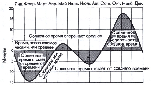
I had to drive all these calculations into the microcontroller program, I did not dare to write in assembler, so I began to study SI, I had to fiddle with formulas and calculations for weeks to get the right result, studying SI along the way. As a result, I managed to write a working program, while the calculation error does not exceed ±1⁰.
The solar tracker was conceived for a small solar battery with a power of 2W and a voltage of 6V to charge a lithium-ion battery, but it is better to use a more powerful battery of at least 4W. As electric drives, I used MG996R servos (you can buy in China, the link is given at the end of the article). In addition, I purchased special brackets for assembling an alt-azimuth installation (link for ordering at the end of the article). The assembled design allows you to orient the solar battery in height and azimuth, while the azimuth servo is stationary and rotates the height servo together with the brackets.
Below is a diagram of the solar tracker: ![]()
The circuit is based on the PIC16F876A microcontroller, which has a significant amount of memory and contains many peripheral modules. The whole structure is powered by a Li-ion battery, which is accordingly charged from a solar battery through a module based on the TP4056 chip, this is a specialized charge controller for Li-ion batteries (order link at the end of the article). To determine the current time and date, the scheme uses a module (link for ordering at the end of the article). The clock is quite accurate, the time drift is ± 2 minutes per year, I already wrote a detailed article about them, those who wish can familiarize themselves. To display the parameters, a digital indicator is used on (link for ordering at the end of the article).
The maximum voltage on the Li-ion battery does not exceed 4.1V, which is not enough to power the servos, so a step-up module based on the MT3608 chip has been added to the circuit (order link at the end of the article). The minimum input voltage of the module is 2V, the maximum load current is 2A, the module has a multi-turn variable resistor to adjust the output voltage. To save energy, the power to the servos is not constantly supplied, but only to change the position of the shaft. The power is switched using a p-channel field-effect transistor VT1, the converter module is also controlled from the microcontroller.
The module board does not provide a contact for control, so it is necessary to additionally solder the wire to the 4th pin of the MT3608 chip, this is the on / off input of the converter. On the board, this pin is connected to the “+” power supply, first you need to cut the tracks suitable for this pin (for this you will have to unsolder the microcircuit), or raise the pin above the board. A voltage divider resistor chip is installed on the module board, increasing the resistance of this resistor will also reduce consumption in sleep mode, I replaced it with another one, with a resistance of 9.1 kOhm, initially it was 2.2 kOhm. After replacement, you need to set the output voltage to about 5-5.5V to power the servos, the figure below: 
The clock module also needs to be improved, to reduce power consumption, you need to solder the 24c32 memory chip, the “POWER” LED, as well as the resistor (200 Ohm), through which the external supply voltage is supplied to the battery, why the Chinese did this remains incomprehensible, because the battery is not intended for charge, see picture below: 
The HL1 LED is set to indicate a communication error with the DS3231 clock (via the I2C interface), the LED starts blinking if there is no response from the clock.
The assembly of the alt-azimuth setup should be started when the servos are set to the middle position, this happens when the device is first turned on, the indicator will show the inscription “Cent”. It is desirable to mount the azimuth servo on a plate that will serve as the base of the installation, or on a stand, so that the output shaft is directed vertically upwards. Next, you need to attach the height servo bracket, first you need to screw the sliding sleeve to the bracket, then the adapter sleeve. The bracket must be set perpendicular to the long side of the azimuth servo, as shown in the photo: 
When assembling, it is difficult to achieve a perpendicular position, but this is not necessary, deviations within ± 5-10 degrees are acceptable. In the future, software adjustment will eliminate this deviation.
After fixing the height servo, it remains to fasten the carrier bracket, first try on the adapter sleeve on the servo shaft, select a position so that the carrier bracket after installation is directed vertically upwards. Again, it is not necessary to set the exact position, as I said earlier. A general view of the installation is shown in the following photo: 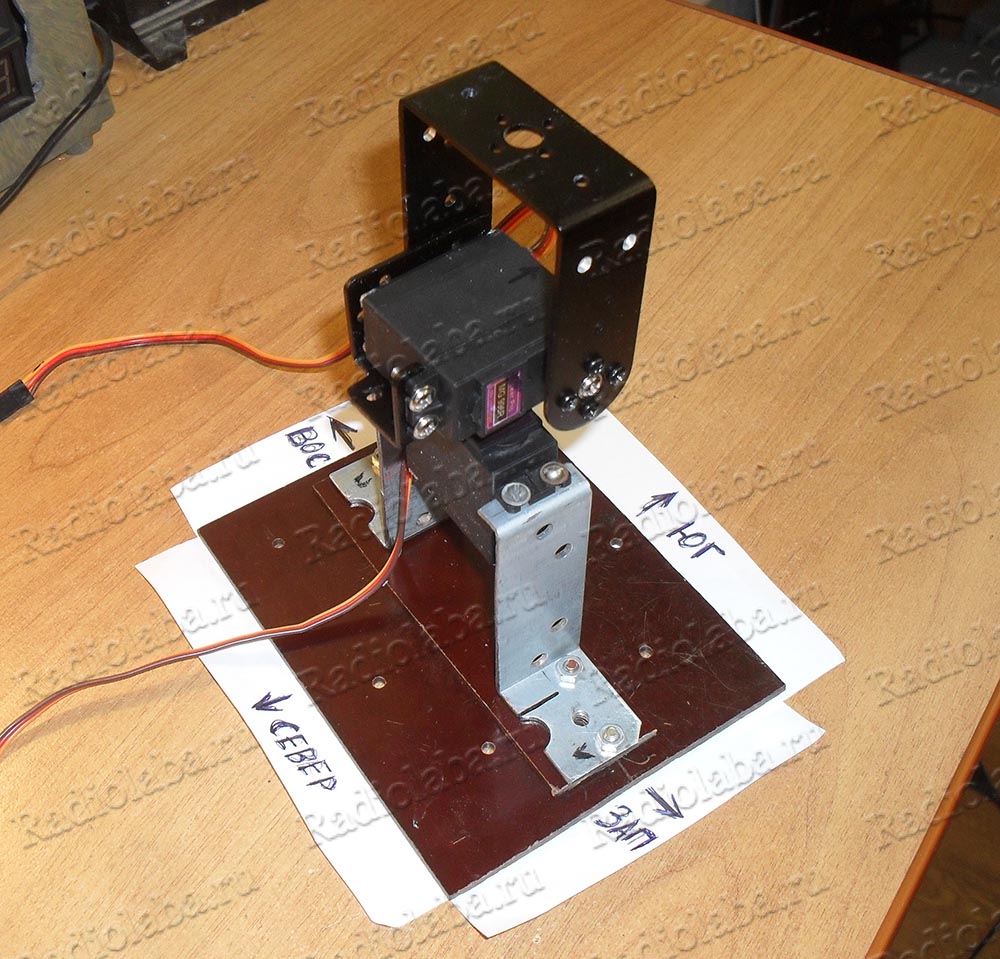
The following is the procedure for adjusting the extreme positions of the servos. Adjustment should be performed on a flat surface, when the servo shaft is azimuthally vertical (the axis of rotation is directed along a plumb line). After pressing the “Enter” button, the supporting bracket turns towards the conditional North and takes a horizontal position (the inscription “north” is displayed on the indicator): 
If there is a deviation from the horizontal, then you need to adjust the position of the bracket using the “Set” and “Discharge” buttons. Thus, the extreme position of the servo is adjusted. Further, when the “Enter” button is pressed, the bracket turns towards the conditional South (South is written on the indicator). If necessary, adjust the horizontal position of the bracket as described above.
Further pressing of the “Enter” button will turn the arm towards the conventional East (on the indicator there is an inscription EASt). The “Set” and “Discharge” buttons correct the direction, while it is convenient to focus on the body of the azimuth servo drive, it is necessary that the bracket be directed along the long side of the body, when viewed from above: 
The next time you press the “Enter” button, the bracket will turn towards the West (the indicator shows the inscription WESt), the adjustment is performed as described above.
As a result of the correction, the bracket is rotated in height and azimuth within 180⁰, the correction values are stored in the microcontroller's EEPROM memory. After pressing the “Enter” button, the bracket will take the corrected direction to the conditional South. For the correct orientation of the solar battery, the direction to the conditional South should indicate the real point of the South in the given area, and the servo drive shaft in azimuth is located vertically along a plumb line.
After pressing the “Enter” button again, the time, date, time zone, location coordinates, and duration of sleep mode should be set. Accordingly, for each parameter, the following inscriptions are displayed on the indicator:
– local time, by default 0 h 0 min;
– location longitude, by default -0 deg. 0 min. (for western longitude, a minus sign “-” is put);
– location latitude, by default -0 deg. 0 min. (for the southern latitude, a minus sign “-” is put);
– time zone, by default -0, (for western longitude a minus sign “-” is put);
– sleep mode duration, default 1 min.
The “Discharge” and “Set” buttons set the parameter values, when the “Enter” button is pressed, the time and date values are written to , the rest of the parameters are stored in the EEPROM memory of the microcontroller. After entering all the parameters, the indicator displays the inscription SUCCES (for 1 second, then the indicator goes out), then the installation is aimed at the Sun, according to the entered parameters.
To save energy, aiming at the Sun is performed after a certain period of time, which is set in the Sleep mode duration parameter. After pointing, the servos are de-energized, the microcontroller goes into sleep mode, the total consumption of the tracker is reduced to 160 μA. The duration of "sleep" can be set within 1-255 minutes.
When the tracker is turned on again (after turning off the power), the EEPROM memory is first checked, if the saved parameters are correct, the tracker continues tracking the Sun, while the digital indicator remains in sleep mode and does not turn on to save energy. You can generally turn off the power of the indicator after the initial input of parameters. To re-enter the correction mode, you need to hold the “Set” button and power on the tracker. If the parameters read from the EEPROM are incorrect or missing, it will also enter the correction mode.
I additionally added the function of outputting the main parameters via the UART interface to the microcontroller program. After calculating the position of the Sun, the microcontroller transmits the current value of time, date, serial number of the day, location coordinates entered during setup, as well as the current values of the height and azimuth of the Sun. Each parameter starts with the symbol “$” and ends with the symbols “\r”, “\n”. This data can be viewed on a computer by connecting the tracker via a USB-UART adapter. In the settings of the terminal program, you need to set the following settings: baud rate 9600 bps, 8 data bits, one stop bit. Below is a screenshot from the terminal program: ![]()
MG996R servos are not protected from moisture inside the case, so in case of outdoor use, the servos must be sealed. Remove the four bolts from the underside of the case, and apply neutral silicone sealant between the joints of the case, and apply sealant around the cuff to enter the wires into the case. You can additionally apply grease to the gears of the gearbox, since the factory one is practically absent. According to reviews, SHRUS-4 grease is best suited, unlike lithol, it does not freeze in the cold. To seal the upper hole, a silicone ring can be put on the output shaft, and the chamfer must be removed from the adapter, which is installed on the shaft, so as not to create excessive friction.
I attached a rectangular textolite plate to the supporting bracket, on which I glued the solar battery using double-sided tape. Since the servos are de-energized most of the time, it is possible to rotate the shaft in height under the influence of the gravity of the solar array. To avoid this, I attached long counterweights made of angles and plates to the sides of the carrier bracket. By changing the mass of the counterweights, I balanced the structure along the axis of rotation of the height.
The tracker performs guidance when the Sun is above the horizon, that is, when its height is greater than 0⁰. When the Sun sets below the horizon (negative altitude value), the tracker directs the solar array to the East, further tracking resumes at sunrise. Tracking is performed over the entire visible region of the sky.
The daily movement of the Sun and stars can be viewed on a computer in the Stellarium program, a free virtual planetarium that displays a realistic starry sky. The program displays the movement of the luminaries in the sky, you can see the position of the Sun and stars at any time, data on various coordinates is also available.
I mounted the device on a printed circuit board that I designed to fit the GAINTA G1202G case. The board has a place for a jumper (jumper), with which you can turn off the power of the digital indicator.
Field effect transistor VT1 can be replaced with IRLML2244, IRLML6402. You can also use transistors in the SOIC-8 package (you will have to redo the board): IRF9332, IRF9310, IRF9317.
At negative temperatures, Li-ion batteries lose significant capacity (electrolyte freezes), it is not recommended to use batteries at temperatures below +5 ⁰C, as this leads to premature reduction of the resource. Therefore, if you plan to operate the tracker in frosty weather, it is better to use a LiFePO4 lithium-iron-phosphate battery. Batteries of this type are more frost-resistant, the operating temperature range is from -30 ⁰C to +55 ⁰C, the maximum voltage is 3.65V, the minimum is 2V, the average is 3.3V, that is, lower than that of Li-ion. Also, the advantages include a stable discharge voltage close to 3.2V. At the end of the article are links for ordering a battery, as well as a module for charging.
On the basis of a solar tracker, you can create a small autonomous system that does not require external power, such as a remote weather station, or a security system for a summer house, etc. You can replace the servos with more powerful ones, and install a larger solar panel. It is possible to adapt the circuit for solar panels at 12, 18V, to charge several series-connected batteries, but for this you will have to change the circuit and use other charge modules.
Below are links for ordering modules and components for assembling a solar tracker:
Solar battery 6V 4.5W
Real time clock module DS3231
Digital indicator on MAX7219 driver
Li-ion battery charge module on TP4056
Battery LiFePO4 6500mah
Battery LiFePO4 1800mah
LiFePO4 battery charge module
Servo MG996R
Brackets for assembling alt-azimuth installation for MG996R servos
Boost converter on MT3608
![]()
![]()
![]()
![]()
![]()
![]()
To begin with, it is probably worth telling what this article means by a solar tracker. In short, the device is a movable stand for a solar panel, which is necessary so that in our temperate latitudes the panel collects a sufficient amount of light, changing its position following the sun.
In this case, the prototype solar tracker was assembled on the basis of Arduino. To rotate the platform in the horizontal and vertical axes, servo drives are used, the angle of rotation of which depends on the power of the light incident on the photoresistors. Everyone's favorite Soviet metal constructor is used as the body.
It would be useful to mention that all this was done as a course project, so I did not bother to purchase and mount the solar panel itself and the battery, since their presence is not related to the work of the tracker. As an excuse, I can say that the possibilities of the Soviet metal constructor are immense, so screwing a small solar panel to it to charge the phone will not be difficult if such a desire arises.
So, what was used in the assembly:
The speaker, who suddenly appeared on the list, was required to heighten the high-tech effect. The fact is that the servos can only rotate 180 degrees, and we don’t need more, given that we are following the sun. But when testing the project, when you can’t really follow the sun for two minutes of the demonstration, it turned out that it would be nice to signal at what point it is worth stopping waving the flashlight, because the servo has reached the dead zone. For this, the above call was added.
So, let's start collecting the tracker. To begin with, let's divide the upcoming front of work into conditional four stages: assembling the stand for solar panels and mounting servos, attaching light-sensitive elements to the assembled structure, soldering and writing code for Arduino.
The photoresistors are quite securely attached to the body, the only thing that would be worth working with is the accuracy of their location on the platform: now they do not look up perpendicular enough, which can upset perfectionists and slightly spoil the accuracy of rotation.
A bit of circuitry: the connection of photosensitive elements is carried out according to the voltage divider circuit, for which the output resistors indicated in the list of elements were required. All photoresistors are soldered to a common pin connected to the Arduino's five-volt power output. For convenience and aesthetics, the legs of the photoresistors are soldered to the contacts of two three-core insulated wires (one contact remained unused and hidden). All circuitry details can be seen in the diagram below.


The code
#include

The “bang-bang” channel showed how to make a homemade solar tracker for panels. They will automatically rotate after the sun, increasing the efficiency of the power plant.
You will need two solar panels with a capacity of 3.5 watts each. At the output, one has more than 6 volts, which, when two batteries are connected in series, will give more than 12 volts. USB socket on the back. Three outputs from three battery segments. Each of which generate 2 volts. That is, if necessary, you can connect accordingly and get 2, 4, 6 volts.

The next important node is two servos. One will rotate the solar array horizontally and the other vertically. These drives are not simple, they are not so easy to make rotate. Some improvement is needed. In the set with each of the engines are plastic crosses, discs, screws for fastening. Brackets purchased for the engine. Also included are mounting screws, bearing and discs. charge controller. It will receive energy from solar panels and transfer it to the battery.
Let's start working with our own hands with electronic filling. The tracker diagram for the solar panel is below.  Wiring diagram, board, board editing program: https://cloud.mail.ru/public/DbmZ/5NBCG4vsJ
The circuit is very simple and easy to repeat. It is the most successful of several proven options. But even her author had to change a little. I had to change the values of variable and fixed resistors, a printed circuit board circuit was designed.
To begin with, let's print out the circuit board of the tracker on special paper. This is laser ironing technology. The paper has a glossy appearance. On the reverse side, it is the usual matte. You need to print on a laser printer on the glossy side. After contact with the iron, it must be allowed to cool and the paper easily comes off the layer.

Before transferring, the textolite must be degreased. It is best to use fine sandpaper. We attach the pattern to the board and iron it with a hot iron for 2 minutes.
Now you need to etch the tracker board. Ammonium persulfate can be used. Sold in radio stores. The same solution can be used several times. It is desirable to heat the liquid to 45 degrees before use. This will greatly speed up the etching process. After 20 minutes, the board was successfully completed. Now you need to remove the toner. Again, use sandpaper or acetone.
Now you can make a hole in the board. You can start soldering parts.
The heart of the solar tracker is the lm324n operational amplifier. Two transistors type 41c, type 42c. One ceramic capacitor 104. The author of the development replaced many details with the smd type. Instead of 5408 diodes, their analogues of the smd type were used. The main thing is to use at least 3 amps. One resistor for 15 kilo-ohms, 1 for 47 kilo-ohms. two photoresistors. 2 tuning resistors for 100 and 10 kilo-ohms. The latter is responsible for the sensitivity of the photo sensor.
 A heliostat, or otherwise, a tracker, is a device for tracking the sun, in our case, for turning solar panels so that they are always perpendicular to the sun. It's no secret that it is in this case that the solar panel gives maximum power. In the diagram above, the solar tracking device (heliostat) uses pulse control and, without any human assistance, is able to orient the solar array to the best illumination.
The heliostat circuit consists of a clock generator (DD1.1, DD1.2), two integrating circuits (VD1R2C2, VD2R3C3), the same number of shapers (DD1.3, DD1.4), a digital comparator (DD2), two inverters (DD1. 5, DD1.6) and a transistor switch (VT1-VT6) for the direction of rotation of the electric motor M1, which controls the rotation of the platform on which the solar battery is installed. With the power on, the generator on the elements DD1.1, DD1.2 generates clock pulses that follow at a frequency of about 300 Hz. When the device is in operation, the durations of the pulses generated by the inverters DD1.3, DD1.4 and the integrating circuits VD1R2C2, VD2R3C3 are compared. Their steepness varies depending on the integration time constant, which, in turn, depends on the illumination of the photodiodes VD1 and VD2 (the charging current of capacitors C2 and C3 is proportional to their illumination). The signals from the outputs of the integrating circuits are fed to the level shapers DD1.3, DD1.4 and then to a digital comparator made on the elements of the DD2 microcircuit. Depending on the ratio of the durations of the pulses input to the comparator, a low-level signal appears at the output of the element DD2.3 (pin 11) or DD2.4 (pin 4). With equal illumination of the photodiodes, high-level signals are present at both outputs of the comparator. Inverters DD1.5 and DD1.6 are required to control transistors VT1 and VT2. A high signal level at the output of the first inverter opens the transistor VT1, at the output of the second - VT2. The loads of these transistors are keys on powerful transistors VT3, VT6 and VT4, VT5, which switch the supply voltage of the electric motor M1. The R4C4R6 and R5C5R7 circuits smooth out ripples at the bases of the control transistors VT1 HVT2. The direction of rotation of the motor changes depending on the polarity of the connection to the power source. The digital comparator does not allow all key transistors to open at the same time, and thus ensures high reliability of the system.
In the morning with sunrise, the illumination of the photodiodes VD1 and VD2 will be different, and the electric motor will begin to turn the solar panel from west to east. As the difference in the duration of the pulses of the shapers decreases, the duration of the resulting pulse will decrease, and the speed of rotation of the solar battery will gradually slow down, which will ensure its accurate positioning in the sun. Thus, with pulse control, the rotation of the motor shaft can be transmitted directly to the platform with a solar battery, without the use of a gearbox. During the day, the solar panel platform will rotate with the movement of the sun. With the onset of twilight, the duration of the pulses at the input of the digital comparator will be the same, and the system will go into standby mode. In this state, the current consumed by the device does not exceed 1.2 mA (in orientation mode, it depends on the motor power).
If the design is supplemented with a vertical deflection block assembled according to a similar scheme, it is possible to fully automate the orientation of the battery in both planes. If suddenly there were no microcircuits indicated on the diagram, they can be replaced with microcircuits of the K564, K176 series (with a supply voltage of 5 ... 12 V). Transistors KT315A are interchangeable with any of the KT201, KT315, KT342, KT3102 series, and KT814A - with any of the KT814, KT816, KT818 series, as well as germanium P213-P215, P217. In the latter case, resistors with a resistance of 1 ... 10 kOhm should be connected between the emitters and bases of transistors VT3-VT6 to prevent their accidental opening due to a significant reverse current. Instead of photodiodes FD256, you can put pieces from solar cells (connected with polarity), phototransistors without bias circuits, as well as photoresistors, for example, SF2, SFZ or FSK of any modification. It is only necessary to select (by changing the resistance of the resistor R1) the frequency of the clock generator according to the reliable operation of the digital comparator. A green light filter is used to protect the photodiodes from excessive irradiation. An opaque curtain is placed between the photo sensors. It is fixed perpendicular to the board in such a way that when the angle of illumination changes, it obscures one of the photodiodes. 


