A microphone is a device that converts sound vibrations into electrical current. In sound transmission, the microphone is the primary link in sound reception. A microphone is a useful device that can be used to communicate on the Internet, as well as to record voice or sounds (instruments, special effects). However, high-quality microphones cost a lot of money, and cheap ones will not be able to provide sufficient sensitivity and quality.
In this article, we will tell you how to make a microphone suitable for daily use with your own hands.

Of course, making a condenser microphone for vocals or podcasts with your own hands is almost impossible - their device is too complicated, which can become a hindrance for a person who is poorly versed in electronics.

Electret microphones are much simpler in design and therefore more reliable. In addition, the small size and low cost of electret microphones allow them to be used almost anywhere where sound reception may be required.


Here is an easy way to make such a microphone with your own hands.

To make it easier for you to navigate, look on the Internet for photos of a homemade microphone or a standard electret microphone (“labeled”).

That's it, your homemade microphone is ready! You managed to create a sensitive measuring microphone with your own hands, which is also well suited for communication.

As a rule, expensive and high-quality microphones are bought for serious work or hobbies, whether it is professional sound recording, broadcasting or vocals.


In the vast majority of cases, for comfortable work and for the closest access to the sound source, you have to additionally purchase a special stand for such microphones. Now we will tell you how to make a desktop microphone stand at home.

Lamp on the clamp - can be purchased at any electronics store. Attention: the mass of the lamp must correspond to the mass of your microphone, otherwise the microphone on a weak clamp will easily fall under its own weight.

The holder depends on the type of your microphone: for a dynamic microphone, a holder can be purchased at a price of 250 rubles, for a condenser (spider type) - at a price of 500 rubles.

It is possible to find and purchase an adapter for a microphone holder for easy installation on a clamp.


Ready! Now you have a convenient adjustable microphone stand that can be easily attached to the table, and the clamp design allows you to screw a pop filter and other accessories to it.


Working with electrical appliances has always been considered a difficult task. Usually only people who have enough experience or have been trained in this in educational institutions are engaged in it. We are used to buying equipment in specialized stores, so few people think about making various types of devices on their own. Of course, you can repair something yourself, but for the manufacture of equipment at home, you need skill.
If you have the necessary equipment and materials, experience in this field and the desire to design something and save the family budget, you can try to find interesting ideas on the Internet. There you will find many interesting ideas and tips on how to make devices better.
In our article, we will consider one of the studio devices that can be used for personal use. We will talk about microphones and how to create them with your own hands at home. We will consider all the pros and cons of this method.
IMPORTANT: Working with electronics and electrical appliances carries risks and potential health hazards. We recommend that you refrain from working if you are not confident in your skills and abilities in the field of electrical appliances.
A person is able to create almost anything he wants, nature has awarded him with inimitable intelligence and the ability to fantasize. A microphone for a computer is far from the most complex device of the possible inventions of mankind. But it is worth considering the level of your abilities and skills. It is from them that the final result of all work will depend.
 If you are seriously thinking about creating a unique microphone, you should provide the workflow with all the necessary tools and materials in advance. To do this, you need to purchase:
This is quite enough to create a homemade version of the device. No expensive elements, only the most necessary for normal functioning. This method will help you save money, since good equipment in stores is very expensive, and cheap models usually have poor parameters and characteristics of the resulting sound.
IMPORTANT: The appearance of the microphone will turn out to be unusual and will differ from the store options. If you wish, you can purchase additional parts for the case or look for old non-working devices and take spare parts from them.
After you have prepared everything for manufacturing, you can proceed to the most difficult stage of work. Be especially careful when performing the sequence of manipulations with electronics. All points for convenience are described in detail in the instructions below:
IMPORTANT: If there is no result, the problem may be in the places of soldering. Try to take everything apart and re-solder the wires to the capsule and plug.
 It is difficult to determine and say the exact service life for home-made things, unlike purchased ones. You will not have a warranty for this product, so you will also repair and extend its performance yourself. Depending on a number of factors, the period of use will also change. Among the main parameters affecting the duration of operation, the following can be distinguished:
Try changing specifications and using different materials to compare and choose the best option.
It’s very difficult to do without a computer microphone now, you can’t use voice search without it, you can’t chat with a friend via video link. However, not all computers have built-in microphones, moreover, they often do not have very good sensitivity. You can solve this problem quite simply - assemble the microphone yourself.


(downloads: 206)


You can not only play around with voice search on Google (there are a lot of extensions for the Chrome browser for this, they are almost all the same, they use the same thing, but it seemed to me the most convenient extension “Voice search 2.02 - a microphone icon appears in all input forms by clicking on which can be said or dictated rather, for example, a search query as in the picture) but already with speech recognition somehow, but still work.
From Siri on Apple, I didn’t manage to achieve some kind of reciprocity, to the extent that it could be “used” for something serious, all the same, “imprisonment” for English affects, and I already know the addresses of the nearest dumplings. In any case, Google remains the leader in speech recognition, voices, it's a pity there is no way to use it programmatically and in Russian.
So the main weak point of microphones is sensitivity, and then of course the price.
Here is an example of how you can get around these two restrictions and for very little money, and if you have the details listed below, then for free, get a fairly sensitive home-made microphone. A photo of how to do it yourself, a description of the work and a microphone diagram below.
Made by me homemade microphone has high sensitivity and is able to perceive even the ticking of the clock at a distance of several meters. It also allows you to record high-quality sound using a computer. The recording quality also depends on the capabilities of the sound card in the system unit. In the design of the microphone unit, components of end-of-life electronics are used to the maximum.
An electret microphone can be taken from any old radio (in extreme cases, from a mobile phone). I used two microphones at once (+), which made it possible to significantly expand the sound perception diagram. The signal from the microphones, amplified by the low-noise transistor VT1, is fed to the operational amplifier DA1 (see Fig. drawing - microphone diagram). The amplifier output can be connected to ordinary headphones or fed further to signal recording and processing devices (desktop computer, laptop, etc.).
Drawing 1. Microphone diagram
The microphone amplifier is powered by the battery of any old mobile phone. Its battery life is tens of hours. You can use a free USB port on your computer to charge the battery. The amplifier can be left constantly connected to the port, since the charging current is small. I took the wire with the USB connector from the mouse. The connector at the output of the amplifier used 03.5 mm, - as for headphones - from any player, the volume control - too, and the rest of the details, including the SA1 power switch, - any small-sized ones.
All components should be placed on a small fiberglass board (photo 1 - above). I glued a small piece of foam rubber to the battery, and laid the board on top (photo 2). All this was well pulled off with electrical tape and tried on the regulator knob (photo 3). Then, to eliminate interference and interference, such a “sandwich” was placed in a tin screen, which was soldered to a common wire (photo 4, 5).
Microphones must be fixed in a piece of dense soft material. After that, in a piece of foam rubber (which, for example, is used for washing a car), I cut out a niche and inserted the entire block into it (photo b, 7), and pulled a fabric cover over it (photo 8). It is only necessary to provide slots for the plug, switch and volume control.
 1 PC. handmade felt homemade fabric flowers craft feltro…
14.05 rub.
Free shipping★★ ★★ ★★ ★★ ★★ (4.80) | Orders (268)
I have already described one design of a microphone designed for the DPC, but its operation revealed a number of shortcomings, which are described below. So I tried to make a better model.
The result is two different microphones, one mono and the other stereo.
 |
 |
 |
 |
My first homemade microphone had a too uneven frequency response due to the resonance that occurs in the tube. In addition, it allowed recording only monophonic sound. It was decided to build a more perfect model of the microphone, but, as always, do without turning and milling.
In the course of reflection, several ideas came up for making a slot microphone tube without the use of machines, and even the tube itself.

The slot microphone tube can be made from large diameter washers. If two holes are drilled in each washer, then you can use two pins to assemble a multilayer sandwich, and adjust the size of the slots with small washers.
This idea, in my opinion, has only one significant drawback. In order to drill holes in each washer with sufficient accuracy, a small jig would have to be made.

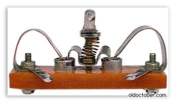
If instead of washers you use clamps from old-type transistors, then you won’t have to drill anything at all. It remains only to collect the tube.

The disadvantage of a pipe assembled from standard clamps from transistors of the type P213 ... P217 is a lot of weight. If you use duralumin clamps from transistors of the KT801 type, you can get a fairly light tube. True, it will be difficult to place two microphone capsules in such a tube at once, so for a stereo wet phone you will have to look for another solution.

The slit microphone tube can be made from a narrow metal tape by rolling it into a helix on a template of the desired diameter. Then the width of the slots can be adjusted by changing the pitch of the screw.
Based on these ideas, I made two microphones - monophonic and stereophonic.
This time I omitted some details regarding the assembly of microphones and the manufacture of parts, since I have already covered them in detail.
This is a drawing according to which a slit microphone was made from transistor clamps.

It turned out to be easy to assemble a microphone from clamps from transistors. Here's what was used for the build.


In order to make the appearance more presentable, I covered the body of the microphone, made from a syringe, with heat shrink tubing. First I seated the front part, and at the end of the assembly I inserted the cover and seated the tail part.

Here's what happened.
This is a drawing from which a directional stereo microphone was made from a metal tape.

Very few parts were needed for this microphone.


In order not to deal with painting, I covered the steel tape with heat shrink tubing, and then rolled it into a helical spiral pos. 1 on the body of a 10 gram syringe.
From the body of a 20-gram syringe, I made the microphone body pos.3, and the baffle pos.2 from the piston of the same syringe.
At this stage, you can drill three holes for attaching the tube to the body and cut the threads.

To reduce the length of the unshielded wires going to the microphone capsules, I extended the stereo cord with two small pieces of mono cord. The picture shows how it was done. Thick paper is used as insulation.

The microphone housing, as in the previous design, was covered with heat shrink tubing.

Another picture explaining the assembly order.

Here's what happened.
| Get the Flash Player to see this player. | ||
And here's how it works.
When testing the first pair of microphone capsules, it turned out that their frequency response differed too much. In anticipation of the market day, I even assembled a small stand to test microphones without using soldering. I bought a few more capsules for $ 0.4, so that I had plenty to choose from. But, the very first pair taken from this purchase turned out to be consistent in frequency response. I didn't experiment anymore.


