China provides for a small price a huge amount of not only electronic devices, but also their components. A small array of light emitting diodes can show the information you need, presumably numbers, since the resolution is not very high, 8 by 8 LEDs, each diameter 3 mm. This matrix shines in red, because it is the most visible and attracts attention more than other colors.


If you have several such matrices on LEDs, you can connect them to create large information boards.


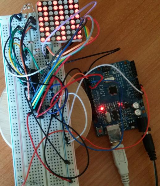
Matrix display - a device consisting of an 8x8 LED matrix and a control board based on the MAX7219 chip with the minimum required piping. In the photo you can already see the finished device, but it came to me by mail in this form, so I had to pick up a soldering iron and solder everything in the right way.

The basic connection to the Arduino Nano board is shown in the circuit diagram.

As you can see from the diagram, everything is simple, you just need to connect the contacts of both boards with wires in the following order:
| Arduino Nano | Matrix 8x8 |
| PIN 12 | PIN DIN |
| PIN 11 | PIN CLK |
| PIN 10 | PIN CS |
| PIN 5V | PIN 5V |
| PIN GND | PIN GND |
So, finally it's time to work with the code, and in order to run the LED matrix, you need to download and install the LedControl library. The library supports MAXIM 7221 and 7219 microcircuits. The LED matrix uses MAX7219 as a driver, this is what we need. I think we should start with a small sketch demonstrating the basic functions of this library. In the sketch, the setRow() function is used to turn on/off the LEDs. The syntax for calling the setRow() function is:
matrix.setRow(0, row, col, set);
Where matrix- class object LedControl
0 - address of the device on the SPI bus, in this case there is only one device, and the numbering starts from address zero
row- row(Possible values from 0 to 7)
col- column (Possible values are from 0 to 7)
set- setting value( true- turn on, false- switch off)
matrix.setRow(0, 1, 4, true)
Turn on the LED on the matrix, located in the 1st row and in the 4th column.
Another example:
int x = 1;
int y = 4;
matrix.setRow(0, x, y, true);
matrix.setRow(0, x, y, false);
The same is only with the use of variables, and the subsequent turning off of the lit LED at the given coordinates. So, in the sketch, several animations are played using the setRow () function.
#include "LedControl.h" //Syntax for creating the LedControl class(dataPin,clockPin,csPin,numDevices) //Where LedControl is an object of the class //dataPin is the pin on the Arduino board to which the DIN pin will be connected //clockPin is the pin on the board Arduino to which the CLK pin will be connected //csPin - the pin on the Arduino board to which the CS pin will be connected //numDevices - the number of devices on the bus //Create an object of the matrix class in our case with one connected device LedControl matrix = LedControl(12, 11 , 10, 1); //Delay time for turning on/off the LED on the matrix const int delayValue = 100; //Function prototypes //Sequential on/off void PointSerialSet(); //Snake from right to left void PointRigthToLeft(); //Snake from bottom to top void PointDownToUp(); //Snake from left to right void PointLeftToRigth(); //Snake from top to bottom void PointUpToDown(); //Effect - fading pulse void PointFading(); //Effect - pulse void PointPulse(); //Effect - growing impulse void PointClimbing(); //Effect of twisting the spiral inside void PointToSpiralIn(); //Effect of spinning the spiral outward void PointToSpiralOut(); void setup() ( // Device with address 0 wake up by default matrix.shutdown(0, false); //Set the brightness of the Led matrix to 8 //Possible values are from 0 to 15 matrix.setIntensity(0, 8) ; //Clear display matrix.clearDisplay(0); ) void loop() ( //Call functions one by one PointSerialSet(); PointRigthToLeft(); PointDownToUp(); PointLeftToRigth(); PointUpToDown(); PointFading(); PointPulse() ; PointClimbing(); PointToSpiralIn(); PointToSpiralOut(); ) //Function bodies void PointSerialSet() ( //Use the setLed(address, row, col, set) function //Sequential switching on by rows for(int i = 0; i< 8; i ++) { for(int j = 0; j < 8; j ++) { //Включить светодиод matrix.setLed(0, i, j, true); delay(delayValue); //Выключить светодиод matrix.setLed(0, i, j, false); } } } void PointRigthToLeft() { //Используем функцию setLed(address, row, col, set) //Змейка справа - налево for(int i = 7; i >= 0; i --) ( for(int j = 7, n = 0; j >= 0, n< 8; j --, n ++) { if((i % 2) >0) ( matrix.setLed(0, j, i, true); delay(delayValue); matrix.setLed(0, j, i, false); ) else ( matrix.setLed(0, n, i, true); delay(delayValue); matrix.setLed(0, n, i, false); ) ) ) ) void PointDownToUp() ( //Use the setLed(address, row, col, set) function //Snake from bottom to top for(int i = 7; i >= 0; i --) ( for(int j = 7, n = 0; j >= 0, n< 8; j --, n ++) { if((i % 2) >0) ( matrix.setLed(0, i, n, true); delay(delayValue); matrix.setLed(0, i, n, false); ) else ( matrix.setLed(0, i, j, true); delay(delayValue); matrix.setLed(0, i, j, false); ) ) ) ) void PointLeftToRigth() ( //Use the function setLed(address, row, col, set) //Snake from left to right for(int i = 0 i< 8; i ++) { for(int j = 7, n = 0; j >= 0, n< 8; j --, n ++) { if((i % 2) >0) ( matrix.setLed(0, j, i, true); delay(delayValue); matrix.setLed(0, j, i, false); ) else ( matrix.setLed(0, n, i, true); delay(delayValue); matrix.setLed(0, n, i, false); ) ) ) ) void PointUpToDown() ( //Use the setLed(address, row, col, set) function //Snake from top to bottom for(int i = 0 i< 8; i ++) { for(int j = 7, n = 0; j >= 0, n< 8; j --, n ++) { if((i % 2) >0) ( matrix.setLed(0, i, n, true); delay(delayValue); matrix.setLed(0, i, n, false); ) else ( matrix.setLed(0, i, j, true); delay(delayValue); matrix.setLed(0, i, j, false); ) ) ) ) void PointFading() ( //Use the setLed(address, row, col, set) function //Fading effect int upValue = 0; int downValue = 7; for(int i = 0; i< 8; i ++) { if(i % 2) { for(int n = downValue; n >= upValue; n --) ( matrix.setLed(0, n, i, true); delay(delayValue); matrix.setLed(0, n, i, false); ) downValue --; ) else ( for(int j = upValue; j< downValue + 1; j ++) { matrix.setLed(0, j, i, true); delay(delayValue); matrix.setLed(0, j, i, false); } upValue ++; } } } void PointClimbing() { //Используем функцию setLed(address, row, col, set) //Эффект затухания int upValue = 4; int downValue = 4; for(int i = 0; i < 8; i ++) { if(i % 2) { for(int n = downValue; n >= upValue; n --) ( matrix.setLed(0, n, i, true); delay(delayValue); matrix.setLed(0, n, i, false); ) downValue ++; ) else ( for(int j = upValue; j< downValue + 1; j ++) { matrix.setLed(0, j, i, true); delay(delayValue); matrix.setLed(0, j, i, false); } upValue --; } } } void PointPulse() { //Используем функцию setLed(address, row, col, set) //Эффект пульса for(int i = 0; i < 8; i ++) { if(i == 4) { for(int climb = i; climb >= 0; climb --) ( matrix.setLed(0, climb, i, true); delay(delayValue / 4); matrix.setLed(0, climb, i, false); ) for(int fade = 1; fade< 8; fade ++) { matrix.setLed(0, fade, i, true); delay(delayValue / 4); matrix.setLed(0, fade, i, false); } } else { matrix.setLed(0, 4, i, true); delay(delayValue); matrix.setLed(0, 4, i, false); } } } void PointToSpiralIn() { //Используем функцию setLed(address, row, col, set) //Эффект спирали внутрь int lengthX = 8; // Ширина матрицы int lengthY = 8; // Высота матрицы int pointX = 0; int pointY = 0; int dir = 0; // Направление (0 - вправо, 1 - вниз, 2 - влево, 3 - вверх) int offset = 0; // Смещение // Перебираем всю матрицу for (int i = 0; i < lengthX * lengthY; i++) { matrix.setLed(0, pointY, pointX, true); delay(delayValue); matrix.setLed(0, pointY, pointX, false); if(dir == 0) { pointX ++; if(pointX >= lengthX - 1 - offset) ( dir = 1; ) continue; ) if(dir == 1) ( pointY ++; if(pointY ><= offset) { dir = 3; } continue; } if(dir == 3) { pointY --; if(pointY <= offset + 1) { dir = 0; offset ++; pointY = offset; } continue; } } } void PointToSpiralOut() { //Используем функцию setLed(address, row, col, set) //Эффект спирали внаружу int lengthX = 8; // Ширина матрицы int lengthY = 8; // Высота матрицы int pointX = 3; //начать с этих координат int pointY = 3; //начать с этих координат int dir = 0; // Направление (0 - вправо, 1 - вниз, 2 - влево, 3 - вверх) int offset = 3; // Смещение // Перебираем всю матрицу for (int i = 0; i < lengthX * lengthY; i++) { matrix.setLed(0, pointY, pointX, true); delay(delayValue); matrix.setLed(0, pointY, pointX, false); if(dir == 0) { pointX ++; if(pointX >= lengthX - 1 - offset) ( dir = 1; ) continue; ) if(dir == 1) ( pointY ++; if(pointY >= lengthY - 1 - offset) ( dir = 2; ) continue; ) if(dir == 2) ( pointX --; if(pointX<= offset - 1) { dir = 3; } continue; } if(dir == 3) { pointY --; if(pointY <= offset - 1) { dir = 0; offset --; pointY = offset; } continue; } } }
Video of the sketch:
This article was created for those who bought a bare 8x8 matrix and 74hc595 shift registers and do not know how to connect it all.
I searched the Internet for a long time for instructions on how to connect the above components, but I found either not for my registers or with non-working sketches, so I decided that I still have to work with my hands and head to please myself with 8 * 8 pictures.
Having found datasheets for the matrix and shift registers on the Internet, I drew the following diagram:
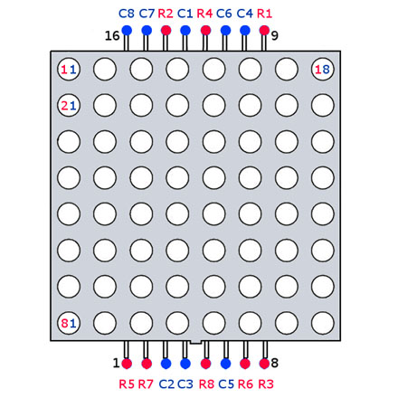
The 12th leg of both microcircuits (latch pin), to save ports is common, because it makes no sense to latch the registers at different times. Some of the matrix pins (anodes) are connected through current-limiting resistors with a nominal value of 220 ohms. Everything else according to the scheme is extremely simple. Just in case, pictures with the pinout of the matrix.

Images will have to be displayed line by line (otherwise with similar matrices there is no way), with a small delay (the human eye practically does not distinguish between a delay of 1ms).
I tried to explain everything in the sketch. When uploading to the board, the display will show the numbers that we will send to the arduino port monitor. (See video)
Photo of the finished device (zigzag on the screen, in the sketch its image is stored in the pic array)
In the future I will try to do something interesting on this display.
Finally, matrix modules arrived from China. Each module consists of a MAX7219 chip (), an LED matrix, one capacitor and one resistor are in the harness.

Controlled by MAX7219 via SPI interface.

Microcircuits in a cluster are connected in series. I read on the Internet that the maximum possible serial connection allows only 8 pieces of MAX7219. Don't believe. 16 modules connected, and everything works fine.
The modules presented on Ali come in several versions. The most popular are 2 types: with a microcircuit in DIP and in SOIC packages. The DIP chip module is larger and not as convenient when connected in a cluster. You will have to connect a bunch of wires.

Modules with a chip in a SOIC package are the size of an LED matrix and are connected by soldering or jumpers. It turns out nice and neat.

The most well-known libraries for working with matrices and clusters are MAX72xx Panel by Mark Rice and Parola by MajicDesigns: The first library is easier to use, the second is more complex with more features. I'll write it out in more detail.
Library installation required when using MAX72xx Panel Adafruit GFX.
To Russify the text, you will need to download THIS FILE and replace the default glcdfont.c file in the Arduino/Libraries/Adafruit-GFX-Library-master directory. Also in this file, in addition to the necessary letters and numbers, a bunch of all sorts of characters are described. Not all of them may be useful. The picture below explains how the symbols are formed.

If necessary, you can create your own symbols and replace them with any unused ones in the file. Almost all bitmap fonts used in various libraries are formed in this way.
So, the MAX72xx Panel and Adafruit GFX libraries are installed, the glcdfont.c file is replaced. Launch Arduino IDE, open FILE. There is a utf8rus function in the sketch. It provides recoding of the character table for the Russian language. It is needed only for normal output from the program, that is, in the program, the desired text is written in Russian. If the text is entered via the COM port, then the character codes are corrected in the Serial_Read function. In the IDE and in the console, the developers used different encodings.
At the beginning of the file there are lines necessary for the library to work.
int numberOfHorizontalDisplays = 1;
int numberOfVerticalDisplays = 16;
I have modules with a chip in a SOIC package. They have a small feature. The matrix of the modules is installed rotated by 90 degrees. It's a convenience fee. If you run the sketches that come with the libraries, they will output text from bottom to top in each module. The text will be displayed in zigzags. To treat this ailment, the library needs to be "told" that there are 16 vertical displays (they are physically located horizontally). And then in void Setup specify the line for the library
matrix.setRotation(matrix.getRotation() + 1);
It will programmatically flip each matrix. And everything will be displayed normally.
Modules with a DIP chip package do not have this. Everything is beautiful, except for a bunch of wires.
The MAX72xx Panel library is rather modest. There are no visual output effects. The cluster is perceived as one whole. Things are much better with MD Parola.
Owners of modules with a chip in a SOIC package will also face the problem of orienting modules in a cluster. Only it looks a little different than in MAX72xx. Here, the modules will appear, as it were, out of turn.

HelloWorld sketch from samples included with the library.
Programmatically in the sketch, I was not able to cure this ailment. I treated him differently. In the file Adruino/libraries/MD_MAX72xx_lib.h at the end you need to find the lines as in the picture.

And fix the selected line selected 1 to 0. Save the file. Arduino IDE does not need to be restarted. We pour, we look.

Now you can use 24 animation effects. The animation is started with the command P.displayText(“Text to display”, “text alignment”, speed, display delay, fade-in effect, fade-out effect). As you can see, there are a lot of settings.
And the most relish is the division of the cluster into virtual zones. Working with zones is not very difficult. I don’t post the sketch, it is in the samples that come with the library. Now you can display the clock at the beginning of the cluster and the news ticker on the remaining modules without any problems, almost.
As you may already guess, the problem is with Cyrillic letters. She is also resolvable. Next to the previous file in the same directory is the file MD_MAX72xx_font.cpp. This is a font file. The characters in it are formed similarly to the library's GFX font file. There is a slight difference. Here the character size can be less than 5 points. In the Adafruit GFX library, the exclamation mark, for example, takes up the same 5 dots as wide as any other symbol, only one row of dots is used. The rest do not glow, but are used as a symbol. In Parola, the same exclamation mark also occupies one row of dots, only there are not empty dots nearby, but adjacent characters can be. It will be clearer to understand the picture.

There is no time to supplement the file with Cyrillic characters similarly to the file from the first considered library. If someone does this and sends me a file, I will add it to this article, and both I and the guests of my site will be grateful to you.
Outcome. The MAX72xx Panel library by Mark Rice is easy to use and understand, but with poor functionality.
The Parola library from MajicDesigns is more complex and has enough capabilities for almost any application.
In previous lessons, we learned with the help of a shift register. This turned out to be a little more difficult than directly from general purpose pins. The problem that we then had to solve was the limited number of controlled outputs on the Arduino controller. The apogee of our research was the use of dynamic indication for. Now it's time to complicate the task a little more: we are learning to work with the LED matrix.
 Suppose the task is to light the R6C3 LED. To do this, we need to apply a high signal level to pin R6, and connect pin C3 to ground.
  Without turning off this point, let's try to light another - R3C7. Connect the positive power pin to R3 and ground to C7. But in this case, rows R6 and R3 will intersect with columns C3 and C7 not in two, but in four places! Consequently, not two, but four points will light up. Problem!
  Obviously, the same can help. If we turn on the points R6C3 and R3C7 in turn very quickly, we can use the persistence of vision - the ability to interpret rapidly changing images as a whole.
  Focusing on the lesson about dynamic indication, let's try to use 8-bit shift registers in the matrix indicator control scheme. We connect one register to the indicator outputs responsible for the columns, and the second to the row outputs. circuit diagram
 Important note #1. It is necessary that the resistors in this circuit be on the lines coming from the first shift register. This shift register is responsible for the columns. With this connection, each resistor will set the current for only one LED at each step of the dynamic algorithm. Therefore, all LEDs will glow evenly. Important note #2. The diagram above is for informational purposes only. It would be more correct to include an additional power microcircuit in the gap between the second register and the matrix, for example, the ULN2003 transistor assembly.
  The first shift register will be responsible for the columns, and the second for the rows. Therefore, the output of a string will consist of two consecutive writes to the register: first we pass the code of the string, then the code of the points in this string. In this program, we will also use an accelerated version of the digitalWrite function. This is necessary in order for the dynamic indication process to proceed very quickly. Otherwise, we will see a noticeable flickering of the matrix. Source const byte data_pin = PD2; const byte st_pin = PD3; const byte sh_pin = PD4; unsigned long tm, next_flick; const unsigned int to_flick = 500; byte line = 0; const byte data = ( 0b00111100, 0b01000010, 0b10100101, 0b10000001, 0b10100101, 0b10011001, 0b01000010, 0b00111100 ); void latchOn()( digitalWriteFast(st_pin, HIGH); digitalWriteFast(st_pin, LOW); ) void fill(byte d)( for(char i=0; i<8; i++){
digitalWriteFast(sh_pin, LOW);
digitalWriteFast(data_pin, d & (1<
The first shift register will be responsible for the columns, and the second for the rows. Therefore, the output of a string will consist of two consecutive writes to the register: first we pass the code of the string, then the code of the points in this string. In this program, we will also use an accelerated version of the digitalWrite function. This is necessary in order for the dynamic indication process to proceed very quickly. Otherwise, we will see a noticeable flickering of the matrix. Source const byte data_pin = PD2; const byte st_pin = PD3; const byte sh_pin = PD4; unsigned long tm, next_flick; const unsigned int to_flick = 500; byte line = 0; const byte data = ( 0b00111100, 0b01000010, 0b10100101, 0b10000001, 0b10100101, 0b10011001, 0b01000010, 0b00111100 ); void latchOn()( digitalWriteFast(st_pin, HIGH); digitalWriteFast(st_pin, LOW); ) void fill(byte d)( for(char i=0; i<8; i++){
digitalWriteFast(sh_pin, LOW);
digitalWriteFast(data_pin, d & (1<