In addition to the rheostatic and direct methods of starting induction motors, there is another common method - switching from star to delta.
The star-delta switching method is used in motors that are designed to operate when the windings are connected in a delta. This method is carried out in three stages. At the beginning, the motor is started when the windings are connected in a star, at this stage the motor accelerates. Then they switch to the working triangle connection scheme, and when switching, you need to take into account a couple of nuances. First, you need to correctly calculate the switching time, because if the contacts are closed too early, the electric arc will not have time to go out, and a short circuit may also occur. If the switching is too long, then this can lead to a loss of motor speed, and as a result, an increase in the current surge. In general, you need to clearly adjust the switching time. In the third stage, when the stator winding is already delta connected, the motor goes into steady state operation.
The meaning of this method is that, when connecting the stator windings with a star, the phase voltage in them decreases by 1.73 times. In the same number of times, the phase current that flows in the stator windings also decreases. When the stator windings are connected in a triangle, the phase voltage is equal to the linear voltage, and the phase current is 1.73 times less than the linear one. It turns out that by connecting the windings with a star, we reduce the linear current by 3 times.
In order not to get confused by the numbers, let's look at an example.
Suppose the working circuit of the winding of an asynchronous motor is a triangle, and the linear voltage of the supply network is 380 V. The resistance of the stator winding is Z \u003d 20 Ohm. By connecting the windings at the time of star start, we reduce the voltage and current in the phases.

The current in the phases is equal to the linear current and is equal to

After accelerating the engine, we switch from a star to a delta and we get other values \u200b\u200bof voltages and currents.
As you can see, the line current when connected in a triangle is 3 times more than the line current when connected in a star.
This method of starting an asynchronous motor is used when there is a small load, or when the motor is idling. This is due to the fact that when the phase voltage decreases by 1.73 times, according to the formula for the starting torque which is provided below, the torque decreases by a factor of three, and this is not enough to start with a load on the shaft.

Where m is the number of phases, U is the phase voltage of the stator winding, f is the frequency of the mains current, r1, r2, x1, x2 are the parameters of the equivalent circuit of the asynchronous motor, p is the number of pole pairs.
Content:
Asynchronous electric motors have proven themselves in operation with such indicators as reliability in operation, the ability to obtain high torque power, and excellent performance. An important indicator of the operation of these motors is the ability to switch to a star and delta connection - and this is stability during operation. Each connection has its own advantages, which must be understood in the correct application of asynchronous motors.
The transformation of a "star" into a "delta" in an asynchronous electric motor, as well as the ability to repair the windings of an electric motor, and, compared with other motors, low cost, combined with resistance to mechanical stress, made this type of motor the most popular. The main parameter that characterizes the dignity of asynchronous motors is simplicity in design. With all the advantages of this type of electric motors, it also has negative aspects during operation.
In practice, three-phase asynchronous electric motors can be connected to the network according to the "star" and "triangle" schemes. The "star" connection is when the ends of the stator winding are wrapped at one point, and the mains voltage of 380 volts is applied to the beginning of each of the windings, schematically this type of connection is indicated by the sign (Y).

If the “triangle” option is selected in the switching box for connecting the electric motor, the stator windings must be connected in series:

Experts, without going into the basics of electrical engineering, cite the fact that electric motors connected according to the “star” scheme work softer than those connected according to the triangle (Δ) scheme. This is a good circuit for small engine power. They also highlight the fact that during soft operation, when the star (Y) circuit is used, the electric motor does not gain its nameplate power.
When choosing the best option for connecting an electric motor, one should consider the fact that the delta connection (Δ) allows the motor to gain maximum power, but the value of the starting current increases significantly.
Comparing the power indicators, this is the main difference between the star and delta connections (Y, Δ), experts note that electric motors with a star connection (Y) have a power 1.5 times lower than those connected with a delta (Δ).
To reduce the current parameters at the moment of start-up in different switching circuits (Δ) - (Y), it is recommended to use the star-delta connection of the motor, a combined switching circuit. Combined, or it is also called mixed, the type of connection is recommended for electric motors with a large nameplate power.

When the star connection (Y) and (Δ) is switched on, the star connection (Y) works from the beginning of the start, after the electric motor has gained sufficient speed, it switches to the delta connection (Δ). There are devices for automatically switching motor connections. Let's consider how the starting schemes of electric motors differ and what is the difference between them.
Often, to start a high-power electric motor, switching the delta connection to a star is used, this is necessary to reduce the current parameters during start-up. In other words, the engine is started in the "star" mode, and all work is carried out on the "delta" connection. For this purpose, a three-phase contactor is used.

It is necessary to fulfill the prerequisites for automatic switching:
The time delay is necessary for 100% disconnection of the star connection, otherwise, when the connection is turned on, a delta will occur between the phases. A time relay (RT) is used, which delays the switching by an interval of 50 to 100 milliseconds.

When a star and delta circuit is used, it is imperative to delay the connection on time (Δ) until the connection is turned off (Y), experts prefer three methods:


The classic version of switching from a "star" to a "triangle" is considered by experts to be a reliable method, it does not require large expenditures, it is easy to perform, but, like any other method, it has a drawback - these are the overall dimensions of the RV (time relay). This type of RW is guaranteed to perform a time delay by magnetizing the core, and it takes time to demagnetize it.

The scheme of mixed (combined) inclusion works as follows. When the operator turns on the three-phase switch (AB), the motor starter is ready for action. Through the contacts of the "Stop" button, normally closed position and through the normally open contacts of the "Start" button, which the operator presses, the electric current passes into the contactor coil (KM). Contacts (BKM) provide self-pickup of power contacts and keep them in the on position.


The relay in the circuit (KM) provides the ability for the operator to turn off the electric motor with the Stop button. When the "control phase" passes through the start button, it also passes normally closed contacts (BKM1) and contacts (PB) - the contactor (KM2) starts, its power contacts provide voltage to the connection (Y), the motor rotor starts spinning.
When the operator starts the engine, the contacts (BKM2) in the contactor (KM2) open, this generates an idle state of the power contacts (KM1), which provide power to the motor connection Δ.

The current relay (RT) is triggered almost immediately due to high current values, which is included in the circuit of current transformers (TT1) and (TT2). The control circuit of the contactor coil (KM2) is shunted by the contacts of the current relay (RT), which does not work (PB).
In the contactor circuit (KM1), the contact block (BKM2) opens at startup (KM2), which prevents the coil (KM1) from working.

With the set of the desired parameter of rotation of the motor rotor, the contacts of the current relay open, since the starting current decreases in the control of the contactor (KM2), simultaneously with the opening of the contacts that supply voltage to the winding connection (Y), BKM2 are connected, which brings the contactor (KM1) into working position ), and in its circuit the block of contacts BKM2 opens, and, as a result, the RV is de-energized. The transformation of the "delta" connection into a "star" occurs after the engine stops.
Important! The temporary relay does not turn off immediately, but with a delay, which gives some time in the circuit (KM1) to the relay contacts to be closed, this ensures the start (KM1) and the operation of the engine according to the “triangle” scheme.

Despite the reliability of the classical scheme for switching from one connection to another connection of a high-power electric motor, it has its disadvantages:


An important condition when using the star-delta connection scheme is the correct calculation of the load on the motor shaft. In addition, one cannot deny the fact that when the contactor of one Y connection is turned off, and the engine has not yet gained the necessary speed, the self-induction factor is triggered, and increased voltage enters the network, which can disable other nearby equipment and devices.
Experts recommend that electric motors with an average power value be run according to the Y scheme, this gives soft operation and a smooth start. The methods for selecting the inclusion differ in terms of the available voltage at the facility, and in terms of the load.
Turbine compressor rotor
As you know, three-phase asynchronous electric (el.) Motors with a squirrel-cage rotor are connected according to the star or delta circuit, depending on the line voltage for which each winding is designed.
When starting especially powerful email. delta-connected motors, increased starting currents are observed, which in overloaded networks create a temporary voltage drop below the permissible limit.
This phenomenon is due to the design features of asynchronous email. engines in which a massive rotor has a sufficiently large inertia, and when it is spinning up, the motor operates in overload mode. The start of the electric motor becomes more difficult if there is a load with a large mass on the shaft - the rotors of turbine compressors, centrifugal pumps or the mechanisms of various machine tools.
To reduce current overloads and voltage drops in the network, a special method of connecting a three-phase electric is used. an engine that switches from a star to a delta as it speeds up.
 Connection of motor windings: star (left) and delta (right)
 When connecting star-connected windings of a motor designed for delta connection to a three-phase network, the voltage given to each winding is 70% less than the nominal value. Accordingly, the current at the start of el. motor will be smaller, but it should be remembered that the starting torque will also be smaller.
Therefore, star-delta switching cannot be applied to electric motors that initially have a non-inertial load on the shaft, such as the weight of a winch load or the resistance of a reciprocating compressor.
 It is unacceptable to switch modes with an electric motor standing on a reciprocating compressor
 To work as part of such units, which have a large load at the time of start-up, special three-phase el are used. motors with a phase rotor, in which starting currents are regulated using rheostats.
Star-delta switching can only be used for electric motors with a freely rotating load on the shaft - fans, centrifugal pumps, shafts of machine tools, centrifuges and other similar equipment.
 Centrifugal pump with asynchronous electric motor
 Obviously, in order to start a three-phase electric motor in a star mode, followed by switching to a delta winding connection, it is necessary to use several three-phase contactors in the starter.
 A set of contactors in a star-delta starter
 In this case, it is necessary to block the instantaneous operation of these contactors, and a short-term switching delay must also be provided so that the star connection is guaranteed to turn off before the delta turns on, otherwise a three-phase short circuit will occur.
Therefore, the time relay (RT), which is used in the circuit to set the switching interval, must also provide a delay of 50-100 ms so that a short circuit does not occur.
 Switching time diagram
 There are several principles for implementing a delay using:

 Manual mode switch
 This system is quite simple, unpretentious and reliable, but has a significant drawback, which will be described below and requires the use of a bulky and obsolete time relay.
This RT provides tripping delay due to the magnetized core, which takes some time to demagnetize.
 Electromagnetic delay time relay
 It is necessary to mentally walk through the current flow circuits in order to understand the operation of this circuit.
 Classic switching circuit with current and time relays
 After turning on the three-phase circuit breaker AB, the starter is ready for operation. Through the normally closed contacts of the "Stop" button, and the contact of the "Start" button closed by the operator, the current flows through the coil of the KM contactor. The power contacts of the KM are kept in the on state by "self-pickup", thanks to the BKM contact.
 On the fragment of the above diagram, the red arrow indicates the shunt contact
 The KM relay is necessary to enable the engine to be turned off with the Stop button. The impulse from the "Start" button also passes through the normally closed BKM1 and RV, starting the KM2 contactor, the main contacts of which provide voltage to the star-type winding connection - the rotor is spinning up.
Since at the moment of starting KM2 the BKM2 contact opens, KM1, which ensures that the triangle connection of the windings is switched on, cannot work in any way.
 Contactors providing star (KM2) and delta (KM1) connection
 Starting current overloads el. the motor is forced to operate almost instantly RT, included in the circuits of current transformers TT1, TT2. In this case, the control circuit of the KM2 coil is shunted by the RT contact, blocking the operation of the RV.
Simultaneously with the start of KM2, with the help of its additional normally open contact BKM2, a time relay is started, the contacts of which are switched, but KM1 does not operate, since BKM2 is open in the circuit of the KM1 coil.
 Turning on the time relay - green arrow, switching contacts - red arrows
 As the speed increases, the starting currents decrease and the contact RT in the KM2 control circuit opens. Simultaneously with the disconnection of the power contacts that provide power to the star connection of the windings, the BKM2 closes in the KM1 control circuit and the BKM2 opens in the RV power circuit.
But, since the RV turns off with a delay, this time is enough for its normally open contact in the KM1 circuit to remain closed, due to which KM1 self-picks up, connecting the windings with a triangle.
 Normally open self-pickup contact KM1
 If, due to incorrect calculation of the load on the shaft, it cannot gain momentum, then the current relay in this case will not allow the circuit to switch to delta mode. Long-term operation an asynchronous motor in this mode of starting overload is highly undesirable, the windings will overheat.
 Overheated motor windings
 Therefore, in order to prevent the consequences of an unforeseen increase in load when starting a three-phase el. motor (worn bearing or foreign objects entering the fan, contamination of the pump impeller), you should also connect a thermal relay to the power supply circuit of the electric motor. engine after the KM contactor (not indicated in the diagram) and install the temperature sensor on the casing.
 Appearance and main components of the thermal relay
 If a timer (modern RV) is used to switch modes, which occurs within a set time interval, then when the motor windings are turned on in a triangle, a set of nominal revolutions occurs, provided that the load on the shaft corresponds to the technical conditions for the operation of the electric motor.
 Switching modes using a modern time relay CRM-2T
 The operation of the timer itself is quite simple - first, the star contactor is turned on, and after an adjustable time, this contactor is turned off, and with some also adjustable delay, the triangle contactor is turned on.
When starting any three-phase el. of the motor, the most important condition must be observed - the moment of load resistance must always be less than the starting torque, otherwise the electric motor simply will not start, and its windings will overheat and burn out, even if the star start mode is used, in which the voltage is lower than the nominal.
Even if there is a freely rotating load on the shaft, the starting torque when connected by a star may not be enough and el. the engine will not pick up the speed at which the switch to the triangle mode should be carried out, since the resistance of the medium in which the mechanisms of the units rotate (fan blades or sediment impeller) will increase as the rotation speed increases.
In this case, if the current relay is excluded from the circuit, and the switching of modes is carried out according to the timer setting, then at the moment of transition to the triangle, all the same current surges of almost the same duration will be observed as during starting from a stationary state of the rotor.
 Comparative characteristics of direct and transient engine starts with a load on the shaft
 Obviously, such a star-delta connection will not give any positive results with an incorrectly calculated starting torque. But at the moment the contactor is turned off, which provides a star connection, with insufficient engine speed, due to self-induction, an overvoltage surge will be observed in the network, which can damage other equipment.
Therefore, using star-delta switching, it is necessary to make sure that such a connection of a three-phase asynchronous el is expedient. engine and recheck load calculations.
How to connect a star-delta motor
Enough is written according to the star-delta motor connection diagram. But in every article there are inaccuracies and errors. The authors simply copy each other. I suspect that most of them have never connected the engine in their lives, and the name of the circuit for them is just geometric shapes. Therefore, I decided to follow the folk wisdom “if you want to do it well, do it yourself”, and write this article.
I am speaking from my experience and understanding of the issue. As always, I will give the theory and show how it looks in practice.
To begin with, if someone is not at all in the subject, from what area of knowledge is it all? We are talking about one of the common ways to connect a three-phase asynchronous electric motor, in which the motor windings are first connected to the supply network according to the "star" scheme, and then - according to the "triangle" scheme. In young inquisitive minds, the question will immediately arise - “Why is this necessary?” OK.
The root of the problem lies in the starting currents and excessive loads that the motor experiences when it is powered directly. Why is there an engine - the entire drive rattles and shudders at start-up!
IMPORTANT! If you've read this far, . There is very detailed information about where they come from, how to recognize them, count and measure them.
This is especially critical where there is no reduction gear - a gearbox or a belt on the pulleys.
This is especially important where something massive is planted on the motor shaft - an impeller or a centrifuge.
Subscribe! It will be interesting.
This is especially significant where the engine power is more than 5 kW, and the rotation speed is high (3000 rpm).

These boars do not like when they are included in the network directly
The drive is different from the engine, like a wheel from a tire and how.
So, in order to reduce the power on the motor shaft during start-up, it is first turned on at a reduced voltage, it accelerates slowly, and then it is turned on at full, at rated power. This is implemented not by changing the voltage with rheostats and transformers, but more cunningly. But in order.
Any classic three-phase motor has three stator windings. They may have a different configuration in space, additional conclusions, but there are three of them.

Stator winding diagram with leads for a three-phase asynchronous motor
How to connect all these 6 pins if our power supply has only 3 phases?
In short, here is the simplest scheme:
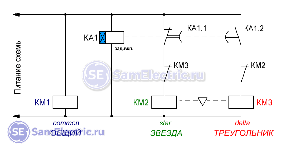
Star-Delta control scheme with time relay. The simplest theoretical
In contacts with a time delay, everyone is constantly confused. I have it right)
What is KM1, KM2, KM3, you already know, but KA1 is a time relay with a turn-on delay. The relay can be any, even electronic, even pneumatic type PVL. The main thing is that the contacts switch from the initial state after a delay time after power is applied to KA1.
You can supply power to the circuit (start the engine) by any means - even with a toggle switch, at least.
The disadvantage of such a scheme is that there is a danger of conflict between KM2 and KM3. Therefore, I do not really like this scheme, because. it works “on the edge”, and its failure-free operation is very dependent on the mechanics and design of the contactors. Because of this, the contacts may burn, and may also knock out the introductory machine. Therefore, a lock is required (electrical and preferably mechanical):
Practical interlocked star-delta arrangement
Blocking is implemented on NC contacts, more about this and more. A mechanical interlock is shown between the coils, not to be confused with the “Triangle” scheme!
This is a real scheme, you can use it. If something is not clear, ask.
By the way, instead of KA1.1, you can put a NO contact with a Delay Delay. That is, it turns on immediately after power is applied, turns off after a while. But this requires two separate time relays with different operating principles, which must be synchronized for a guaranteed pause. This is exactly how it is implemented in specialized Star-Triangle time relays.
Yes, another note. Sometimes the power supply of the common contactor KM1 is not implemented directly, but through the NO contact of the “Star” KM2, then KM1 becomes self-pickup through its NO contact. This is necessary for additional verification of the operability of the time relay KA1.
Timing diagrams for the operation of the Star-Delta circuit
With reference to my control scheme, contactor switching diagrams:
Star-Delta Timing Diagrams
Everything seems to be clear here, but there is one important remark. Again. A small gap (pause) is required between the green and red areas. It may not be present (pause = 0), but these areas can overlap if contactors with a DC coil (=24 VDC) are used. Especially when using a reversed diode (and it is mandatory!), the turn-off time can be 7-10 times longer than the turn-on time!
This is me to the fact that once I was tormented with such a scheme, in it I periodically knocked out an introductory machine. They put a special relay with a pause, the problem was solved!
Real circuit example
Here is a real example of such a circuit on an electronic time relay:
Photo of a star-delta circuit with timer control and galvanic isolation on a transformer.
From left to right in the bottom row: KM1, KM2, KM3, KA1.
And here is an example of a circuit with control from the controller:
Star-delta, compressor, control from the controller program
Video of how the contactors click in this circuit:
Here is how the Germans beautifully designed the scheme in their compressor:
Compressor diagram Star - Delta
There are three wires at the input of the circuit, six at the output. Everything fits.)
How to switch the engine circuit to "Star" and to "Delta" manually
If no automation is needed, and the engine is constantly running in the “Star” or in the “Triangle”, then using an open-end wrench, you can switch the winding connection scheme manually.
Motor rating plate 220 / 380 V 0.37 kW
On the reverse side of the boron lid, as usual, there is a diagram:
Connection diagram 220 - 380 on the motor cover
The motor was fed directly from a three-phase 380 V network through a contactor and was assembled into a “Star:
Motor terminals in connected in the “Star” circuit
We unscrew the M4 nuts, remove the jumpers and power wires:
We disassemble the circuit, discard the wires
We assemble the circuit into a triangle, for a reduced voltage of 220 V:
We assemble a triangular circuit for 220 V
Alteration was needed due to the fact that it is necessary to change the speed of rotation of the engine, and for this, apply a frequency converter. And chastotniki for such power, as a rule, single-phase. As a result - let's go!
By the way, I plan a series of articles on chastotniks, subscribe!
Feature of work in the "Star"
In accordance with GOST 28173 (IEC 60034-1), motors can be operated with a voltage deviation of ± 5% or
frequency deviation ± 2%. In this case, the parameters of the motors may differ from the nominal ones, and the temperature rise of the windings may be more than the limit according to GOST 28173 (IEC 60034-1) by 10 °C.Why am I? The fact is that at start-up, when the engine is running in the “Star”, it does not work in the mode (the voltage differs by 70%!), Which can lead to its overheating if it lasts a long time. Be careful, protect the motor from overheating and overload! But that's another story.)
Video
There are several types of electric motors - three-phase and single-phase. The main difference between three-phase electric motors and single-phase electric motors is that they are more productive. If you have a 380 V outlet at home, then it is best to buy equipment with a three-phase electric motor.
Using this type of engine will allow you to save on electricity and get an increase in power. Also, you do not have to use various devices to start the engine, because thanks to a voltage of 380 V, a rotating magnetic field appears immediately after connecting to the mains.
380 volt electric motor connection diagrams
If you do not have a 380 V network, then you can still connect a three-phase electric motor to a standard 220 V electrical network. To do this, you need capacitors that need to be connected according to this scheme. But when connected to a conventional power grid, you will observe a loss of power. You could read about this.380 V electric motors are designed in such a way that they have three windings in the stator, which are connected in a triangle or star type, and three different phases are already connected to their tops.
It must be remembered that using a star connection, your electric motor will not run at full capacity, but it will start smoothly. When using a triangle circuit, you will get an increase in power compared to a star by one and a half times, but with this connection, the chance of damaging the winding at startup increases.
Before using an electric motor, you must first familiarize yourself with its characteristics. All the necessary information can be found in the data sheet and on the nameplate of the engine. Particular attention should be paid to three-phase Western European-style motors, as they are designed to operate on a voltage of 400 or 690 volts. In order to connect such an electric motor to domestic networks, it is necessary to use only a triangle-type connection.
If you want to make a triangle circuit, then you need to connect the windings in series. It is necessary to connect the end of one winding to the beginning of the next, and then three phases of the mains must be connected to the three connections.
Connecting the star-delta circuit.Thanks to this scheme, we can get maximum power, but we will not be able to change the direction of rotation. In order for the circuit to work, three starters will be needed. On the first (K1), power is connected on one side, and the ends of the windings are connected on the other. Their beginnings are connected to K2 and K3. From the K2 starter, the beginning of the windings are connected to other phases according to the triangle connection type. When K3 turns on, all three phases are shorted and, as a result, the electric motor operates in a star circuit.
It is important that K2 and K3 are not started at the same time, as this may lead to an emergency shutdown. This scheme works as follows. When K1 starts, the relay temporarily turns on K3 and the engine starts as a star. After starting the engine, K3 turns off and K2 starts. And the electric motor starts to work according to the triangle scheme. Termination of work occurs by turning off K1.