This article will focus on the mistakes that can be made when installing RJ45 connectors and the types of damage to the twisted-pair cable used in cable data transmission systems. The figures are shown as examples of faults and do not serve as examples of a correct crimping pattern.
What is a split couple?
A split pair is a serious wiring error in which wires from two different pairs are combined into a "working" pair by mistake (the wires are not twisted together). This fault occurs when the installer confuses the color sequence of the wires in the connector at both ends of the cable in the same way. Data transmission, as before, will be carried out over two conductors, but they will no longer be twisted together.
Why do you need to twist the wires in pairs?
In telecommunications, data is transmitted over wires twisted together - the so-called "twisted pairs". The conductors are twisted to minimize mutual interference and reduce electromagnetic interference. Several twisted pairs in turn form a cable. Pairs even have a different pitch of this twist to lessen the impact on each other. A split pair leads to problems such as line crosstalk, excessive propagation delay between pairs, video interference, bit errors, or data loss.
Will a simple cable tester see a split pair?
Simple cable testers typically test conductors for continuity, electrical continuity, resistance, and capacitance, but do not test for the crosstalk typically associated with split pairs. Accordingly, by checking the cable with a budget twisted pair tester, you will get a good result with an incorrectly mounted line. This is because the check will only be carried out for the possibility of passing current, and since there is such a possibility and the wire numbers at both ends of the cable match, the malfunction will not be detected. A good professional cable tester should be used to detect split pairs. The cable length must be at least 50 cm, on shorter patch cords, it is almost impossible to detect this damage with test equipment, only a visual inspection of the color scheme of the wires will help.
You can detect a split pair with Softing cable testers:
.jpg) Pair break example_1 |
 Pair break example_2 |
A break in a pair, or simply a lack of contact in a UTP, STP, FTP cable, is a simple, common damage. It can be detected by any cable tester paired with a remote ID. The device will send a signal (current) to each conductor, and the counterpart will receive it. If the signal from the main device is not received, then there is no integrity of the wire. The principle of the simplest "dialing" works here. Of course, it is worth mentioning the limitations of the measuring equipment itself, which is designed for a certain maximum cable length, usually at least 305 meters, so that a whole cable bay can be checked. The distance to a break in a pair can be measured with testers that can determine the length of the line by capacitance or by reflectometry (TDR).
.jpg) One wire break example_1 |
 One wire break example_2 |
A broken conductor is also an easily detectable fault. The detection methods are similar to the break of a pair. It is worth noting that testers can recognize the absence of one contact as a break in the entire pair, however, this is not too important, since the line will still have to be repaired.
.jpg) An example of an inverted pair_1 |
 An example of an inverted pair_2 |
An inverted pair is a wiring error on a modular jack or socket (eg RJ45). It may also be called reverse or reversed. Occurs when the wires of one pair are attached to the correct pins on one end of the cable, but reversed on the other end. The core, which at the beginning of the line had serial No. 3 (Fig. An example of an inverted pair_1), at the end of the cable is crimped to contact No. 6, and No. 6, in turn, comes to contact No. 3. This damage can be detected by any tester, but it can only be localized by visually inspecting the connector.
.jpg) Example of crossed wires_1 |
 Example of crossed wires_2 |
The twisted-pair installation error "crossed wires" occurs when the installer, having correctly crimped the connector on one side of the cable, swapped wires from different pairs at the other end. The problem is easily detected even by simple testers. It is solved by repeated, more careful crimping of the connector in compliance with the correct crimping scheme.
If you need to find a malfunction of equipment or electrical wiring, one of the operations that is performed first is to test the cables and wires with a multimeter (tester) to check the health of the circuit (the absence of breaks in it), the presence of a short circuit and determine its resistance (if necessary ). Thus, it is possible to easily and quickly check the lamp, iron, switch, fuse, transformer for serviceability. How to ring the wires with a multimeter correctly will be discussed in this article.
If you plan to ring the wiring in the apartment, you need to know a few fundamentally important facts about multimeters. First of all, it is worth noting that you can check the wire with the simplest device. An inexpensive Chinese model with minimal features is quite suitable.
But at the same time, it is most convenient to use a device that has the dialing function itself. In order to set the device knob to the appropriate position, it is necessary to turn it in the direction of the diode icon (as an option, an image of a sound wave can be additionally applied). This means that when checking the integrity of the wire, an audible signal will sound when the contacts are closed.
But the presence of sound accompaniment is completely optional for the continuity of wires with a multimeter. The fact that the circuit is broken will be indicated by a unit on the display, indicating that the resistance level between the probes is higher than the measurement limit. If there is no damage in the area under study, the resistance value will be displayed on the screen, which should ideally tend to zero (provided that it works in household networks of small length).

network cable continuity with a multimeter
Working with electricity does not allow unprofessionalism, so there is a certain list of rules that allow you to make it as accurate, fast and safe as possible.
When ringing a multi-core cable, it is necessary to separate and strip all existing cores from both ends. After that, you need to check the circuit for the presence of short circuits in it: for this, a “crocodile” is fixed in turn on each core, all the remaining ones are touched with the other measuring end in all possible combinations.

Check if there is a short circuit between the wires of the cable. If there is no sound signal on the indicator “1”, then everything is in order, otherwise there is a short circuit.
In this case, the sound signal will indicate the presence of a short circuit between the wires being tested. This may not be of practical importance for small cross-section multi-core cables operating in low-current networks, but when working with high voltage it is of fundamental importance.

We call the cable cores. There is a sound signal - everything is fine, otherwise - the core is damaged.
To determine the integrity of the cores, the same operation is performed, only at one end of the cable all the stripped cores are twisted together. When looking for a break, it is important to consider that the absence of a sound signal at any of the ends will indicate a violation of the integrity of the conductor.
Consider, as an example, a modern apartment in which the wiring is made in accordance with applicable requirements and standards. This means that when laying the lines for lighting and powering the sockets, they were separated, and separate wires were laid for them in each of the rooms. Each of these circuits is fed from the apartment panel through a separate circuit breaker.
If the light has disappeared in one of the rooms, first you should check the serviceability of the lamp. Before starting work, it is necessary to de-energize the room / apartment, depending on the power scheme. When using an opaque incandescent lamp in a lamp, it is difficult to visually determine the integrity of the filament, so a multimeter and its continuity function are required. Let's see step by step how to do it right.
First you need to check the shield for the presence of triggered machines. In the first case, they will be in the on position (then the malfunction may be hidden in the room switch, lamp or cartridge). The chance of damage to the wiring in such a situation is low. If the device worked, it will be necessary to check everything except the room switch, including the switchboard itself.
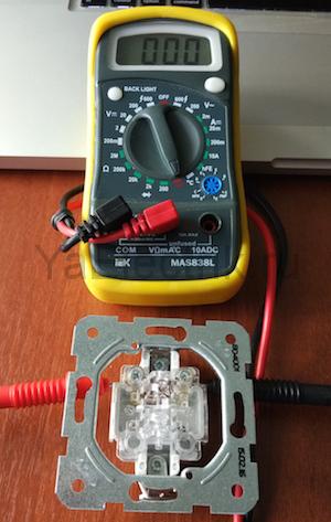
We call the switch. When the switch is on, there should be a sound signal, when it is off - silence and "1" on the indicator.
During such a check, as a rule, a malfunction is detected, which becomes the cause of all the trouble. Its elimination allows you to quickly solve the problem.
To ensure electrical safety during work, in this case, the voltage is turned off using a general apartment machine. Next, the serviceability of the cartridge and the wires connected to the lamp is determined according to the algorithm described above. If there are no malfunctions, you need to check the wiring itself using a multimeter and a continuity function. Such malfunctions happen quite rarely, but they still happen, for example, when installing suspended ceilings or decorative interior elements.
The dialing of the wiring in this case is performed as follows.
From all of the above, we can conclude that the presence of a multimeter with a dialing function in the house is an objective necessity for any home master. With such a device, in most cases it will be possible to quickly eliminate minor malfunctions without seeking help from specialists.
For testing telephone cables and twisted pair patch cords.
This device was taken to check exactly the twisted pair patch cords on the connectors RJ-45. It often happens that in the process of work, a wire is bent somewhere, and some core simply breaks off and stops working. Thanks to this tester, you can easily find which jelly is the problem, and if necessary, re-crimp the entire wire, for example, into 4 wires. It is known that patch cords crimped into 4 wires maintain speed 100mb which is fine for the internet. This is very important if the wire is quite long, it is not clear where the break is, and there is simply no way to buy a new one.
Of course, there are professional testers, which show in which wire and how far the break is, and the length of the wire itself is measured, but this equipment will be relevant for professionals, but such a device is enough for me.
To check, I will use two patch cords, this is a straight line and a cross one. Direct twisted-pair crimp is used to connect a computer to a modem, router, switch, and any other network equipment. This crimp is universal, and supports gigabit speed when using 8 wires, when using 4 wires 100Mb. Crimping it is very simple, the wires match each other, i.e. 1=1, 2=2, etc. The image shows more detail.
For the test, I have a wire with a direct crimp, I will crimp another, the so-called cross crimp. This type of patch cord is used to connect computers to each other without using network switches. The order of crimping the wires can be seen in the image below.

For crimping, we need: crimping tool, two plugs RJ45 and a piece of twisted pair.

We expose the wires according to the picture for cross crimping, cut off uneven edges and insert into the plug.

We put the wire in so that the ends of the wires can be seen from the other end, then, we crimp the wire itself.

Put on and crimped RJ45
In this sequence, we make the second end
Now about the tester itself.
The tester is delivered in a protective case, which is very convenient during operation.
 Power is supplied from a 9 volt crown type element. The tester itself consists of two parts, this is the main "setting part" with LEDs and an operating mode switch, and the response, which shows which wire is ringing now. Parts of the tester can be easily separated from each other.

The switch has 3 positions OFF(switched off), ON(work in normal mode), S(slow switching).
Checking the straight cable.
We connect the cable to the connectors, turn on the tester. Lights from 1 to 8 should light up alternately on both parts of the tester. If at some stage a light bulb does not light up, then there is a break in the same jelly.


Checking the crossover cable.
The situation is more complicated with checking the crossover cable. Since the wires there do not consist alternately, as a result, the bulbs will light up in this order:

If we insert the wire in reverse, the sequence will be reversed. In principle, if the light is on, then the contact is already there.
I was very pleased with the possibility of working without using the counterpart. Instead, it can serve as a network card of a computer or other network equipment.

This means that if you connect one end to the network card, the other to the driving part, the lights will turn on one by one, indicating that the patch cord is working, or vice versa, about a break.
By the way, the RJ45 plug also got on aliexpress:

In the pop-up window on the computer monitor, the inscription “Network cable is not connected” appeared, the LED on the network board does not light up. You insert, remove the RJ-45 plug in the hope of a bad contact in the connection and realize that the cable is faulty. If you do not have a separate network card installed in your computer, and the network cable plug is inserted directly into the motherboard, then the LED will not light if the connection is disabled by software.
Currently, often a twisted pair network cable is first connected to a router, which sometimes freezes. So the first thing you need to do is reboot your router. To do this, just disconnect it from the mains for a minute and then turn it on again. It is possible that Internet access will be restored after that.
Disconnection can occur without your direct participation, for example, due to unstable network voltage, running unlicensed programs or a virus. To check in Win XP, you need to go: Start / Settings / Control Panel / Network Connections and make sure that the connection is connected. Less often, but it also happens that the network card driver does not work correctly. You can check: Start / Settings / Control Panel / System / Hardware / Device Manager / Network cards. There should be no warning signs.
Network cards very rarely fail, this sometimes happens after a strong thunderstorm. You can check the performance of a network card by connecting it to a known good line or installing it in another computer, remembering to install a driver for it. Sometimes it is possible to make the network card work by rearranging it into the adjacent slot of the motherboard.
A call to the technical service of the provider will help to check the operability of the line on their part. If everything is in order in the computer and the provider, therefore, the twisted pair cable has failed and it needs to be repaired. Of course, you can call specialists and wait, but if you wish, it is possible to diagnose and repair the twisted-pair cable with your own hands.
The most likely twisted-pair cable failures are:
- complete breakage of one or more wires - common;
- a short circuit between the conductors of one twisted pair or between the wires of adjacent pairs - is less common.
Search engines often look for the answer to the question: “twisted pair cable test program”. A computer with Windows installed already has such a program that displays the message "Network cable is not connected" in the event of a break or short circuit in the twisted pair cable. You will have to look for the place of a break or short circuit on your own, there is no such program that would indicate exactly the place and cause of the malfunction. There are special testers for this, for example MicroScanner Pro.
Another thing is if there is an Internet connection, but it is unstable or the download speed has suddenly dropped. To monitor network traffic, there is an excellent free program, or rather a utility called Network Traffic Monitor.
It allows you to measure the data transfer rate in real time, observe the change in speed over time, save data on the hard drive, rubber windows, extensive customization options and many other useful services. Supports many languages, including Russian.
Installing the program on your computer is simple, just run the exe file and press the confirmation button several times. Network will automatically be added to startup and will monitor and save all data. To display any of the windows on the monitor screen, just right-click on the tray icon and select the desired window. Network Traffic Monitor is the best utility for analyzing and diagnosing network quality from all that I met while searching. I have tested the Network Traffic Monitor program with Windows HP and Windows 7. You can download the Network Traffic Monitor program with one click of the mouse button from my website.
To test a twisted-pair cable with skill, it is advisable to present an electrical circuit for connecting a twisted-pair cable to a computer network card with other devices, a hub, a switch, or another computer. The figure shows a diagram of a network section for connecting a computer to active equipment, a hub or a switch.

To test a twisted pair cable, it is precisely the part of the network card or hub circuit to which the RJ-45 twisted pair cable connector is connected that is of interest. As you can see, each pair is connected to the transformer in a symmetrical pattern (a tap is made from the middle of the transformer winding, which is connected to a common wire, sometimes through a resistor or capacitor). Thanks to this connection, all induced interference in the cable arrives at the input in antiphase and cancel each other out, while the useful signal arrives in phase and its value does not change. The transformer circuit has another advantage, it protects active equipment from short circuits and tangling of wires in a twisted pair cable when connected.
Some people have a question, what shape and range does the signal have in twisted pairs? In the presented photo, the oscillogram of the information signal. On twisted pairs, both Rx and Tx signals have approximately the same shape and a swing of about two volts. On one pair, the signal is transmitted, and on the second it is received, therefore, two pairs are needed for communication. If one of the RJ-45 connectors on the twisted-pair cable is removed from the equipment, then signal transmission is automatically terminated.

Theoretically, the signal in a twisted pair should have a rectangular shape, but since there is capacitance and resistance of the conductors, the waveform is rounded. For this reason, the distance between communication points is limited, usually no more than 100 meters. The 2 V signal is not dangerous to humans, not dangerous to network equipment and a short circuit between the pairs, so you can troubleshoot the twisted pair cable without disconnecting it from the network. The network card, switch or hub will not fail.
There are several ways to find a break in a twisted-pair cable: external inspection, dialing with a multimeter or pointer tester, and folk methods.
You should start checking the utp cable with an external inspection of the cable along its entire length, special attention should be paid to the quality of the crimp in the RJ-45 plugs. With careless crimping, the conductors may not be fully inserted into the plug, and the contact will be poor. Or the conductors are overlapped with each other at the place of fixation (it happens with a green pair, since its conductors are crimped at a distance of two contacts) and the twisted pairs in this place can close. If visual inspection does not reveal a fault, then the twisted pair cable should be tested.
If you had at your disposal a modern cable tester with an LCD display, for example, MicroScanner Pro, which allows you to determine not only the type of defect in a twisted pair cable, but also its location, or at least a home-made LED tester, then there would be no questions. However, in everyday life you have to do with improvised means.

The easiest way to check is to test the orange and green twisted pair with a switch tester. To do this, remove the RJ-45 plug from the computer's network card. Further, with the probes of the tester, which is switched on in the resistance measurement mode, first touch the orange and white-orange conductor of the twisted pair. The tester should show a resistance of 1-2 ohms, then to green and white-green. The resistance should also be 1-2 ohms. The polarity of the tester connection does not matter. Next, the resistance between the orange and green conductors of the pair is measured. It must be more than 100 ohms, usually equal to infinity. If the measurement results match the above values, then the twisted pairs in the cable are working.
Here is another way that is more complicated, but reliable and indispensable if the twisted pair network cable under test is not connected to the equipment. It is necessary to bring the ends of the cable with RJ-45 plugs into one place and ring the conductors. It is necessary to set the switch on the device to the resistance measurement position and, according to the circuit, check the integrity of the conductors and the absence of a short circuit between them.

The photo shows a twisted pair cable crimped in an RJ-45 connector according to color coding option B.
The end of one probe of the device is touched to the contact of one RJ-45 plug, and the other probe is touched to the contact of the same name of the second plug. The resistance must be zero. The wires of each color are called in turn and each wire is checked for a short circuit with any other. The test for the absence of a short circuit is carried out on one plug. To do this, one end of the probe is connected to the contact, let's say number 1, and the second in turn to all the others. Next, the probe is connected to pin 2 and, in turn, to 3, 4, 5, 6. Since only two pairs are involved in signal transmission (orange and green, plug contacts 1, 2, 3, 6), you need to turn to them when checking Special attention.
But it is not always possible to bring the utp cable connectors to one point. In this case, it is difficult to do without an additional device. Of course, you can extend the end of the tester's probe to the entire length of the cable and test it together, or cut off one of the RJ-45 plugs, strip the wires and twist them together in pairs. But it is more expedient to make the simplest device from an RJ-45 socket, shorting pairs in it with pieces of conductors with a diameter of 0.5 mm or resistors, as shown in the photo. Resistors are better, as this allows you to check not only the integrity of the twisted pair conductors, but also the presence of a short circuit between them. If the measured resistance value is zero, and not installed in the outlet, then the conductors are shorted to each other. It is better to take different resistor values for twisted pair jumpers, for example, 50, 100, 150 and 200 ohms. Then the measurement results will be more informative.

The RJ-45 plug of one end of the twisted pair cable is inserted into the socket with jumpers, touching the probes of the tester to the contacts of the second plug, each twisted pair is checked in turn and there is no short circuit between adjacent pairs according to the technology described above.

Due to the different resistance values, it is easy to check the correctness of twisted pair crimping when checking a newly manufactured cable. If any pairs are reversed, then by the value of the resistance, this will be immediately visible. For example, if when checking the orange pair, the multimeter shows a resistance of 100 ohms instead of the prescribed 50, then instead of the orange pair, another pair is crimped into pins 1 and 2 of the RJ-45, or the cable is crimped in another way.
It is very inconvenient to test a twisted pair cable by touching the RJ-45 plug. If a free RJ-45 socket is available, the measurement conditions can be improved. Insert the other end of the cable into the socket and carry out measurements by touching the probes to the contacts inside the socket.

Based on the results of the audit, a decision is made on further actions. If the orange or green pairs are open or shorted, then you can replace them with one of the unused ones, brown or blue, if they are working. To do this, you will have to cut one plug first and ring all the pairs again, then the second one with a second check of the pairs, since an open or short circuit may be in the plugs themselves. Short circuits occur at the place where the cable is clamped with a retainer in the plug if the wires are not properly prepared. A break if the conductors are notched when cutting the outer sheath of the cable. This is where they often break. If, after cutting the plugs, all pairs turned out to be defective, it is necessary to more carefully inspect the cable along the entire length, if it is not possible to detect a damaged place, you will have to change the twisted pair cable with a new one.
If there is no tester or multimeter at hand, then you can check the health of the twisted pair cable without them using the method below. It is necessary to cut off pieces of 10-15 cm from the ends of the cable, along with connectors. Release the ends of the cable from the sheath by 5 cm and remove the insulation from each of the wires for a length of 2 cm.

Pour a little water with table salt dissolved in it into a small container made of dielectric material (glass, plastic, plastic bag) at the rate of a quarter of the volume of salt from the volume of water. The more salt, the better. Salt is added to water to reduce its electrical resistance. Immerse all conductors of one end of the cable in a container with a solution. You can immerse each twisted pair and in turn. The distance between the conductors of twisted pairs should be minimal, but they should not touch.

Connect the twisted pairs of the opposite end of the cable in series to the poles of any battery or power source with a value of more than 3 V. With a very high salt concentration in heated water, 1.5 V will be enough. This voltage is produced by any AA battery, for example, from a TV remote control. A battery from a cell phone will work with success, it has a voltage of about 3.7 V. A battery from the motherboard will also work, it has a voltage of 3.2 V. If you have a 50-100 Ohm resistor, it is better to connect the battery through it to protect case of a short circuit of twisted pairs. The polarity of the connection does not matter.
The telephone network can be used as a power source. The voltage in the telephone network is about 40 volts and the current is constant, limited at the telephone exchange 40 mA. Such a connection is safe for a person and a telephone line. This option is convenient to use if you need to apply voltage to the twisted pair cable in the entrance, where there is a telephone box nearby.
To check, any charger from a cell phone, a USB port of a computer, at the extreme terminals there is 5 V. It is not permissible to connect to USB without a current-limiting resistor, you can disable the computer. To test twisted pairs, a current of 2 mA is sufficient.

After applying voltage, at the opposite ends of the twisted pair, which are in the water, the following picture will be observed.

As you can see, on the conductor, which is connected to the minus (cathode), small white bubbles of hydrogen are released, and yellow-green bubbles of chlorine are released on the conductor connected to the plus (anode). It is obvious that the pair is in order and there is no short circuit with other conductors. In the event of a short circuit, depending on which wire, white or yellow bubbles also came from the other wire.
If damage is found, then the twisted pair test can be completed at this point and the faulty twisted pair pair can be replaced with a blue or brown one. For example, when checking twisted pairs, a break was detected in the orange pair. Then connect the orange pair coming from the connectors with the blue pair of the cable. The connection technology is described on the Twisted Pair Cable Extension page.
Of course, it is better to crimp the cable with new connectors, rather than splicing. Or crimp in the old way, described on the page "How to crimp an RJ-11, RJ-45 plug onto a twisted pair cable".
If the orange and green pairs are OK and you don't want to mess around with crimping connectors, you need to check the cut pieces of cable with connectors. To do this, all colored wires of twisted pairs and separately white-colored wires, stripped of insulation, are twisted together.

The connector is immersed in the salt solution to such a depth that the contacts are completely in the water. Twisted wires are connected to the battery.

On four of the eight contacts after one, white bubbles should form. You change the polarity of the battery connection, bubbles should form on the contacts on which they did not appear before and also strictly through one. Deviation from this immediately indicates a malfunction. For example, if there are no white bubbles on one of the contacts, then the wire is open, if there is no one on any contact, then there is a short circuit between the conductors. For clarification, you can perform individual testing of pairs by unwinding previously made twists.
Depending on the results obtained, you will have to crimp or splice the wires.
The cable is prepared as described above, only the brine container is replaced with half a potato. Each pair is stuck sequentially into the potato to a depth of 1-1.5 cm. The distance between the conductors should be minimal.

As you can see in the photo, around the wire that is connected to the positive terminal of the battery turned green, and white foam appeared around the negative one. When the wires are removed from the potato, you will notice a darkening of the wire to which the minus was applied. If there are no changes on the cut of the potato, then the twisted-pair conductors are open or shorted to each other.
For the sake of interest, I poked the wires into a slice of an apple. Not so obvious, but that the wires are in order is obvious.

Using the described twisted pair test method, you can test wires of any type, cross section and length.
I have been looking closely at such a device for a long time, tk. in the office I work as a system administrator (if someone is not in the know - a system administrator), there is often a problem with a twisted pair cable (they will press the door, then they will pull it out of the connector, etc.). This is where troubleshooting comes in.
And this tester in a matter of seconds can determine an open, short, or simply incorrect cable crimping.
So, you can connect cables with connectors to the tester - RJ-45 (twisted pair), RJ-11 (telephone cable), USB and BNC (coaxial cable).
Equipment:
1 x Tester
1 x Bag
1 x BNC connector
1 x Instruction 
The device is powered by a “crown” battery, which is not included in the kit (for $ 16 they could have been included in the kit).
The tester itself looks like this: 
There is only one button on it, with the help of which the cable test is carried out, as well as 15 LEDs, which actually serve as indicators.
Tester connectors look like this: 
One part separates: 
Reverse side: 
Battery Placement: 
Since I bought the tester mainly for testing twisted pair, therefore I will describe the operation of the device only on twisted pair, which I will spoil a little (which you won’t do for the sake of review), I think when connecting a telephone cable, USB cable and coaxial cable, the principle will be similar.
We connect the cable to the tester only on one side, if the cable does not have a short circuit, the tester will show " no connection" and the orange LED on the side lights up, the upper LEDs do not light up, the green indicator should always be on, showing the battery charge: 
If the cable is OK, the blue LED will show " connected":
Making a cable break: 
And the blue LED also lights up, but the LEDs on top (orange) will not all light up, signaling " cliff":
Now we make a closure: 
The tester noticed this and reported with a red LED, as well as orange LEDs show which wires " close":
Now we will connect the wires, but mix up the colors: 
We receive the message " non-parallel", but all orange LEDs are on (it would be better if they made an indication of incorrect connection): 
The device also emits beeps:
1 beep - no connection
1 long beep, everything is “ok” (the cable is crimped correctly and there is no short circuit, but a break is not ruled out)
2 beeps - the cable is not crimped correctly
3 beeps - somewhere short circuit
Video:
Now let's analyze the tester: 


The soldering is good, but the soldering liquid is not removed.
Subsuming the results:
- I thought it was a bit overpriced.
- It is a pity that it does not display where the wrong connection is
- No battery
+ Instant result display
+ You can connect not only twisted pair, but telephone cable, USB cable and coaxial cable
+ Included is a case (under the skin)
+ Can measure a cable up to 100 meters long (more than 100 meters cannot be used at all)
+ Intuitive display of results
+ Sound indication
+ Removable panel (you can test the cable 100 meters from the tester itself).
Conclusion: I liked the tester, now it will be easy to determine a break, poor cable compression, as well as a short circuit. If you are not embarrassed by the high price of this tester, you can safely buy it.
NEVER PRESS


