I decided to listen to the class D amplifier on the IRS2092. After a short
searches on Ali an order was made. For the sake of interest “how it sounds”, a timbre block was also ordered for him.
Since the amplifier is still on the road and the tone block has already arrived, I decided
do a review for now on it. When the amplifier arrives, I will review and
him with measurements.
The payment came in an envelope with a bubble wrap. The kit includes the schematic and
four knobs for resistors. Flux veze washed soldering more or less
neat. The board layout is average. The controls in the photo - from left to right - treble, midrange, bass, volume.

NE5532P op amps are installed on the board 
Also on the board are power stabilization circuits (L7812 and L7912) and a rectifier.
You can supply AC voltage from a transformer to power
fees.
The circuit diagram of the regulator is similar to this 
The ratings of some resistors and the absence of some feedthroughs differ.
capacitors.
Now the most important thing is the tests.
Tested on this map 
Creative Sound Blaster X-Fi Titanium PRO with a little refinement - the reverse side of the printed circuit board is completely shielded, the output op-amp is replaced by OPA2134, all power supply capacitors are shunted with ceramics.
Frequency response (in pink - from the input to the output bypassing the tone block, in blue
- through the tone block - all tone controls in the middle position) 
A slight rise in at low frequencies (below 200 Hz) and a blockage at
high (above 6kHz)
Bass controls in extreme positions 
Midrange controls in extreme positions 
Treble controls in extreme positions 
SOI "THD", the right channel goes bypassing the tone block for comparison (from the output of the card to
input), THD of the tone block 0.016%, I would like less of course. I tried to put OPA2134 instead of native op amps, the distortion decreased a little but not significantly, most likely due to not quite correct wiring of the board. 
Dependence of THD on frequency (the right channel goes bypassing the tone block,
pink color on the graph) 
The tone block does not invert the phase of the signal (the right channel goes bypassing the tone block,
pink color on the graph) 
A fairly average block in quality, for home crafts it will go if SOI suits.
I’m unlikely to put in the planned strengthening because of the high
harmonic distortion. I will breed the board myself, and assemble the tone block.
I hope the info was helpful.
Schematic diagrams of simple home-made tone controls (tone blocks), which are made on the transistor KT3102, Kt315 and on the operational amplifier K140UD8 (K140UD20, K140UD12).
Tone block diagrams contain a minimum of details and can be assembled by novice radio amateurs. These timbre blocks can be used in combination with home-made sound-reproducing audio equipment: in bass amplifiers, microphone amplifiers, mixers, etc.
One of the numerous examples of low-frequency and high-frequency tone control circuits for VLF transistors is presented. The above electronic circuit is preceded by a stage with a low output impedance, such as an emitter follower (common collector stage) or an op amp.
This ensures the low output impedance of the previous stage and the normal operation of this regulator.
Rice. 1. Scheme of a two-band tone control (LF, HF) on a transistor.
Elements for the scheme:
Figure 2 shows an example two-way tone control circuits for bass and treble for ULF on an operational amplifier (op-amp). This electronic circuit is preceded by a cascade at the op-amp. This ensures the low output impedance of the previous stage and the normal operation of this regulator.
To increase the stability of the circuit (at RF), it is advisable to shunt the power supply outputs of the op-amp with 0.1 μF capacitors, for example, of the KM6 type. Capacitors are connected as close as possible to the op-amp.
Rice. 2. Scheme of a two-band tone control (LF, HF) on an op-amp.
Elements for the circuit in Figure 2:
A three-band tone control gives better noise reduction than a two-band tone control.
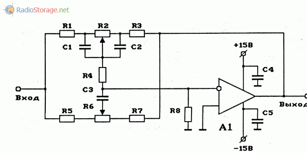
Figure 3 shows an example of a three-band tone control circuit for bass, midrange and treble for VLF on an op-amp. This electronic circuit is preceded by a cascade at the op-amp. This ensures the low output impedance of the previous stage and the normal operation of this regulator.
To increase the stability of the circuit (at RF), it is advisable to shunt the outputs of the power supply of the op-amp with 0.1 μF capacitors. Capacitors are connected as close as possible to the op-amp.

Rice. 3. Scheme of a three-band tone control (LF, MF, HF) on the op-amp.
Elements for the circuit in Figure 3:
Literature: Rudomedov E.A., Rudometov V.E. - Electronics and espionage passions-3.
In many modern audio systems, whether it is a music center, home theater or even a portable speaker for a telephone, there is an equalizer, or, in other words, a tone block. With it, you can adjust the frequency response of the signal, i.e. change the amount of high or low frequencies in the signal. Tone blocks exist active, built, most often, on microcircuits. They require power, but do not weaken the signal level. Another type of timbre blocks is passive, they slightly weaken the overall signal level, but they do not require power and do not introduce any additional distortions into the signal. That is why in high-quality sound equipment, most often, passive tone blocks are used. In this article, we will look at how to make a simple 2-way tone block. It can be combined with a homemade amplifier, or used as a separate device.


(downloads: 742)


Below are schematic diagrams and articles on the subject of "tone block" on the site on radio electronics and the radio hobby site.
What is a "tone block" and where it is used, schematic diagrams of home-made devices that relate to the term "timbre block".
The design of the tone control proposed by the author is used as part of a sound reproducing complex together with the UMZCH described in the article "Superlinear UMZCH of the High-End Class on Transistors" ... and high class. The purpose of the pins of the KA2107 ... chip is used in automotive, portable and stationary sound-reproducing radio and television equipment of medium and high class. An additional control input provides easy volume compensation control. Four control inputs ... The LM1040 chip is used in automotive, portable and stationary sound-reproducing radio and television equipment of medium and high class. An additional control input provides easy volume compensation control. Four control... It is used in stationary and portable sound equipment of medium and high class. Features: 4 high-resistance outputs; the tone for each channel is independently set by external... The two-channel scheme for adjusting volume, tone, balance is designed for use in portable and stationary sound-reproducing equipment of medium and high classes. The purpose of the pins of the TDA1524 chip is given in the table, and the main ones ... The two-channel volume, tone, balance control circuit is designed for use in portable and stationary sound-reproducing equipment of medium and high classes. The pin assignment of the TA7630 microcircuit is given in the table, and the main technical ... The KR174XA53 microcircuit performs the functions of a volume, tone and balance control in stereo systems. KR174XA53 is designed for low-voltage small-sized sound-reproducing equipment with push-button control: radio receivers; cassette, CD and MINIDISC players... The KR174XA54 microcircuit performs the functions of a volume, tone and balance control in stereo systems. KR1 74XA54 is designed for low-voltage small-sized sound-reproducing equipment with push-button control: radio receivers; cassette, CD and MINIDISC players ... K548UN1 - based on this microcircuit, two variants of home-made tone control circuits were assembled. In the first of them (Fig. a), a passive bridge regulator is used to change the frequency response at lower and higher frequencies, and the microcircuit provides compensation for the attenuation introduced by it at medium frequencies. The second device (Fig. b)... Unlike traditional controllers that change the frequency response of the amplifying path at lower and higher frequencies, the parametric controller allows you to shift the frequency response of the frequency response in a fairly wide range. In terms of functionality, such a tone control approaches a multi-band one, but ... The pre-amplifier based on the K140UD1B microcircuit is designed to work in the path of high-quality sound reproduction of signals from various program sources. It is advisable to use it with a power amplifier with a sensitivity of 0.5 ... 1 V with an input resistance of at least 10 ... 20 ... The pre-amplifier circuit on the K284CC2 chip is designed to amplify signals from various program sources. A distinctive feature of the device is the possibility of frequency correction of the amplified signal in separate frequency bands. The amplifier is assembled on a hybrid microcircuit ... A self-made pre-amplifier circuit is designed to work with a high-quality stereo power amplifier with a sensitivity of 0.75 ... 1 V. Each of the pre-amplifier channels consists of a source follower on a V1 field-effect transistor and active volume and tone controls ,... Schematic diagrams of simple self-made tone controls (tone blocks), which are made on the transistor KT3102, Kt315 and on the operational amplifier K140UD8 (K140UD20, K140UD12). Tone block diagrams contain a minimum of details and can be assembled by novice radio amateurs. These timbral blocks... Filters are widely used in audio technology to divide the entire spectrum of the audio signal entering the amplifier input into several bands. This is necessary if the system has a multi-channel, multi-band audio signal processing scheme, for example, to highlight the common low-frequency monophonic ... This design can be made as an independent set of active speakers to reproduce the signal from the output of a personal computer, or used as a repair circuit for repair purchased active speaker with a faulty AF power amplifier circuit. Chip TDA2005 ... The circuit diagram of a self-made three-band tone control, which is made using the op-amp TL082, is considered. This active tone block is suitable for use as part of the UMZCH or as a separate module as part of home-made sound-reproducing equipment. Available on the market... Schematic diagram of a homemade equalizer for 10 bands, built on the basis of operational amplifiers. The equalizer is designed to adjust the frequency response of the ULF, in which it is used, in ten bands with center frequencies: 32 Hz, 64 Hz, 125 Hz, 250 Hz, 500 Hz, 1 kHz, 2 kHz, 4. .. Schematic diagram of a high-quality 10-watt power amplifier with a tone block based on LM1036N, STK436 microcircuits. The amplifier is designed to reproduce the audio signal from the output of various equipment, from an old turntable (with a piezoelectric pickup) to ...It is difficult to imagine a modern low-frequency sound amplifier without a timbre block, and not every modern MP3 player that is a sound source has a high-quality equalizer that fully satisfies the acute hearing of real music lovers. Therefore, I suggest you assemble a simple and fairly high-quality tone block on just one LM1036N chip with your own hands. This microcircuit is installed in expensive audio equipment and works great as a sound preamplifier with almost any low-frequency amplifier.
This figure shows a diagram of a two-channel timbre block with controls: volume, balance, bass timbre, treble timbre and stereo base expander.
In this circuit, the LM1036N chip acts as a low-frequency audio pre-amplifier with volume, balance, low-frequency tone, and high-frequency tone control. A useful feature of the microcircuit is the built-in stereo expander, which allows you to enhance the stereo effect by cross-adding the filtered signals of the left and right channels. I won’t tell you how it works, it’s better to listen with your ears once than read about it a hundred times with your eyes. The voltage regulator L7812CV allows you to power the circuit with a voltage of 12 to 30 volts. It is desirable to assemble the circuit on a printed circuit board, it will be beautiful and reliable. The microcircuit must be carefully soldered, trying not to overheat the legs, otherwise it may fail. In no case do not put the chip in a DIP socket, this will noticeably degrade the sound quality and terrible background sounds will appear. When buying a microcircuit, pay attention to the quality of the marking, the letters must be clear and well read, there are a lot of fakes. I bought in China on Ali Express, they sent 100% new and original. The assembled circuit works immediately and does not need to be configured.
This figure shows the printed circuit board of the tone block on the LM1036N chip.

To test the circuit, I connected a pre-assembled one about which I already wrote in one of my articles to the timbre block. The sound quality is simply excellent, words can not describe it, you just have to hear it. I hope real music lovers will like my homemade product very much. I recommend!

Radio components for assembly
Friends, I wish you good luck and good mood! See you in new articles!


